Crankshaft mounting structure

A technology of installation structure and crankshaft, which is applied in the field of machinery, can solve the problems of affecting the punching accuracy of presses, high assembly requirements, loose split connections, etc.

Inactive Publication Date: 2012-12-19
SHANDONG KING ARROW PRECISION MACHINE
View PDF6 Cites 1 Cited by
  • Summary
  • Abstract
  • Description
  • Claims
  • Application Information

AI Technical Summary

Problems solved by technology

When installing the traditional crankshaft structure, due to the structure of the crankshaft, the crankshaft cannot be directly inserted into the installation. The bearing bush and the part where the bearing bush is installed must be split. In the case of heavy load and long-term impact load, it is easy to cause split connection. The part is loose, resulting in a larger gap between the crankshaft and the bearing bush, which affects the punching accuracy of the press
At the same time, the installation of the split connection is also relatively cumbersome, and the assembly requirements are high, which brings difficulties to the production work.

Method used


Image

  • Crankshaft mounting structure

Examples


Embodiment Construction

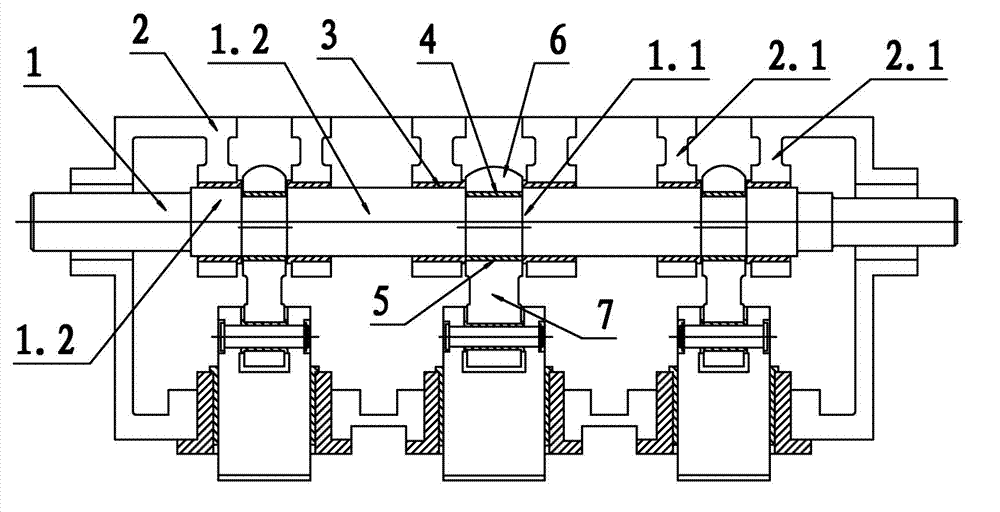
[0010] For ease of description, the crankshaft installation structure of the present invention will be described in detail below in conjunction with the accompanying drawings:

[0011] Such as figure 1 As shown in , a crankshaft installation structure includes a crankshaft 1 and an upper beam 2. The crankshaft 1 has three coaxial pin journals 1.1, and the pin journals 1.1 are equipped with three synchronously moving connecting rods 7 , the two sides of the connecting rod journal 1.1 are the main journal 1.2 provided on the crankshaft 1, the main journal 1.2 is slidingly matched with the main diameter bracket 2.1 provided on the upper beam 2; the main journal 1.2 and the upper beam 2 are provided The main shaft diameter support 2.1 sliding fit means that the main journal 1.2 and the main shaft diameter support 2.1 are also provided with a main bearing bush 3, the inner wall of the main bearing bush 3 is slidingly fitted with the main journal 1.2, and the main bearing bush ...


PUM


Abstract

The invention provides a crankshaft mounting structure, comprising a crankshaft (1) and an upper cross beam (2), wherein the crankshaft (1) is provided with three coaxial connection rod necks (1.1), each connection rod neck (1.1) is provided with three synchronously moving connection rods (7), two sides of each connection rod neck (1.1) are provided with main shaft necks (1.2) arranged on the crankshaft (1), and the main shaft necks (1.2) is in sliding matching with a main shaft radial support (2.1) arranged on the upper cross beam (2). The crankshaft mounting structure disclosed by the invention has the advantages of simple structure and convenience for mounting.

Description

Technical field [0001] The invention involves the field of mechanical technology, especially a pressure machine, specifically a crankshaft installation structure for pressure machines. Background technique [0002] Because the crankshaft of a high -speed pressure machine is a key part of the pressure machine, it plays a role in supporting and passing the tailoring.When the traditional crankshaft structure is installed, due to the crankshaft structure, the crankshaft cannot directly penetrate the installation. The part of the shaft and the installation bearing must be divided.Loose parts, resulting in a large gap between crankshaft and bearing, affecting the accuracy of the pressure machine.At the same time, the connection installation of the division is also cumbersome, the assembly requirements are high, which brings difficulty to the production work. Invention content [0003] The primary technical problem to solve the present invention is to provide a simple and easy -to -ins...

Claims


Application Information

Patent Timeline
IPC IPC(8): B30B15/00B30B1/26
Inventor 吴宏伟黄京鹏
Owner SHANDONG KING ARROW PRECISION MACHINE
Why Eureka
Try Eureka