
Circular inverted cone type bubbling stirred tank reactor

A technology of reaction kettle and inverted cone is applied in the field of bubbling stirring reaction kettle, which can solve the problems of high power consumption, complex structure, and dead angle of stirring.

Inactive Publication Date: 2012-12-19
UNIV OF JINAN
View PDF7 Cites 0 Cited by
  • Summary
  • Abstract
  • Description
  • Claims
  • Application Information

AI Technical Summary

Problems solved by technology

The bubbling and stirring device of the prior art Chinese patent CN201887067U discloses a bubbling and stirring type cashmere tank rehydration device. The air hole realizes the stirring of the material in the reaction tank. This kind of stirring device has disadvantages. One is the vertically upward air outlet, the initial velocity direction is vertically upward, and the floating speed of the bubble is also vertically upward. The upward speed direction of the two-speed synthesis is quickly separated from the reaction interface, and the stirring efficiency is low, so the power consumption is large; second, it is easy to form a stirring dead angle at the bottom of the reactor; third, multiple bubbling stirring parts are placed at the bottom, and the structure is complex and easy to block , not conducive to cleaning
The Chinese patent with the application number 200910252129.0 has a simple structure and is easy to clean and maintain. However, there are also dead spots in the bottom of the reactor and the direction of the initial velocity is vertically upward. The floating speed of the bubbles is also vertically upward. The upward speed direction quickly breaks away from the reaction interface, the defects of large power consumption and low stirring efficiency

Method used


Image

  • Circular inverted cone type bubbling stirred tank reactor
  • Circular inverted cone type bubbling stirred tank reactor
  • Circular inverted cone type bubbling stirred tank reactor

Examples


Embodiment

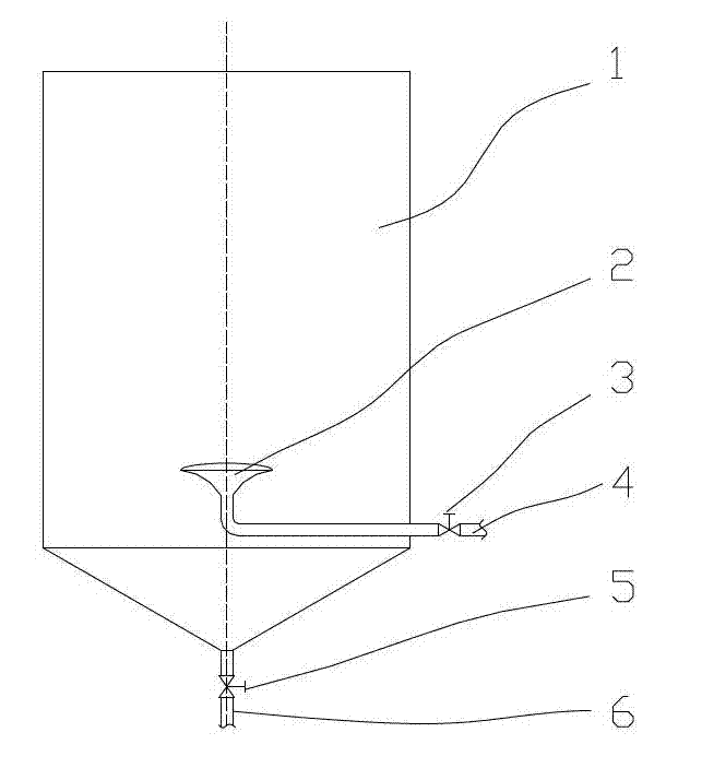
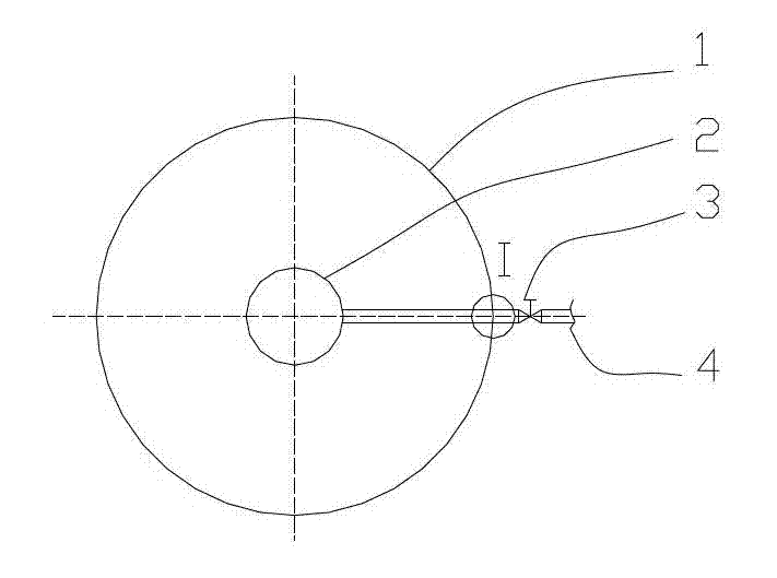
[0023] Arc inverted cone bubbling stirring reactor includes reactor 1, arc inverted cone bubbler 2, inlet valve 3, inlet pipe 4, discharge valve 5, discharge pipe 6, bubbling hole 21, inner tight Fixed screw nut 22, inner gasket 23, outer gasket 24, outer tight nut 25, ordinary fine thread 26, tapered pipe thread 27, characterized in that the center of the lower part of the reaction kettle 1 is equipped with arc inverted cone bubbling Device 2, circular arc inverted cone bubbler 2 is connected to inlet pipe 4, and inlet valve 3 is housed on the inlet pipe 4; The bottom of reaction kettle 1 is connected to discharge pipe 6, and discharge valve 5 is housed on the discharge pipe 6; The arc inverted cone bubbler is characterized in that the outer surface is an arc inverted cone, the bottom surface of the inverted cone is a convex arc surface, the side of the inverted cone is an inward concave arc surface, and the inner concave arc surface There are N bubble holes 21 of equal diame...


PUM


Abstract

The invention relates to the technical field of bubbling stirred tank reactors. A circular inverted cone bubbling stirred tank reactor provided by the invention comprises a reaction kettle, a circular inverted cone bubbler, an inlet valve, an air inlet pipe, a discharge valve, a discharging pipe, bubbling holes, a connecting device, etc. The circular inverted cone bubbler is installed at a central part at the lower part of the reaction kettle and is connected with the air inlet pipe; the air inlet pipe is provided with the inlet valve; the bottom of the reaction kettle is connected with the discharging pipe, and the discharging pipe is provided with the discharge valve; the circular inverted cone bubbler is provided with N bubbling holes with varying directions; the external surface of the circular inverted cone bubbler is in a streamline shape, flowing resistance of a fluid is small, the moving trajectory of agitated bubbles is long, continuous stirring effects last for a long time, and high stirring efficiency is obtained; the bubbling holes are located at the lower part of a circular inverted cone, and bubbles move along an inclined downward direction at first and act on the bottom of the reaction kettle, leaving no stirring dead angle.

Description

technical field [0001] The invention relates to the technical field of bubbling stirred reactors. Background technique [0002] In chemical production, in order to fully mix and react the liquid-solid phase materials, the reaction kettle can be stirred by bubbling. The bubbling and stirring device of the prior art Chinese patent CN201887067U discloses a bubbling and stirring type cashmere tank rehydration device. The air hole realizes the stirring of the material in the reaction tank. This kind of stirring device has disadvantages. One is the vertically upward air outlet, the initial velocity direction is vertically upward, and the floating speed of the bubble is also vertically upward. The upward speed direction of the two-speed synthesis is quickly separated from the reaction interface, and the stirring efficiency is low, so the power consumption is large; second, it is easy to form a stirring dead angle at the bottom of the reactor; third, multiple bubbling stirring part...

Claims


Application Information

Patent Timeline
Patent Type & Authority Applications(China)
IPC IPC(8): B01J8/08
Inventor 马晶王济刚高红鹰于明朱金璇牟宗刚鲍猛王晓轩李平倪献智矫强许崇娟许华芳殷建玲李倩李敏
Owner UNIV OF JINAN
Learn More