
Image processor, image processing method, and program

An image processing device and image-in-image technology, applied in image communication, television, electrical components, etc.

Inactive Publication Date: 2012-12-05
SONY CORP
View PDF2 Cites 9 Cited by
  • Summary
  • Abstract
  • Description
  • Claims
  • Application Information

AI Technical Summary

Problems solved by technology

For example, the production of movies using stereoscopic 3D images is very active

Method used


Image

  • Image processor, image processing method, and program
  • Image processor, image processing method, and program
  • Image processor, image processing method, and program

Examples


no. 4 example (

[0080] 4. Fourth Embodiment (Personal Computer)

no. 1 example

[0082] [Configuration of Image Coding Device]

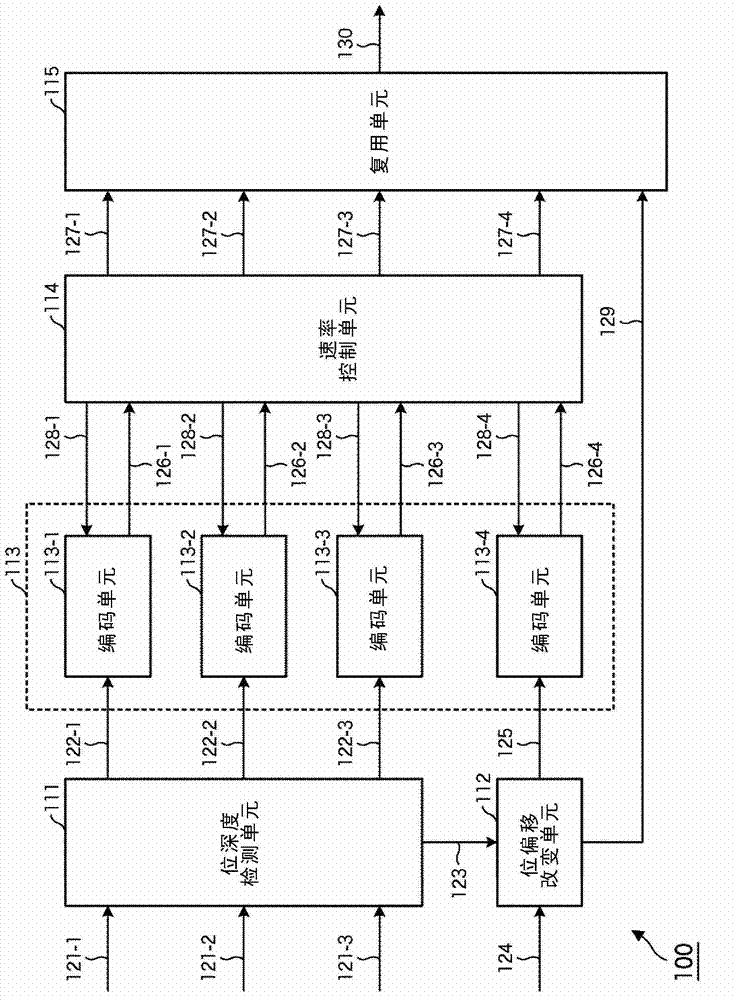
[0083] figure 1 is a block diagram illustrating an example of a main configuration of an image encoding device to which the present invention is applied.

[0084] figure 1 The image coding device 100 shown in is a device for coding image data and depth data of a plane image according to a predetermined coding system, and the depth data indicates that all pixels of the plane image are in the depth direction of the plane image (the depth direction of the plane image position in the front-to-back direction).

[0085] A planar image can be converted into an image corresponding to so-called 3D (dimension (three-dimensional)) with parallax using depth data (hereinafter referred to as a 3D image). Since the positions of all parts in the plane image in the depth direction are represented by depth data, a 3D image generating device that generates a 3D image from a plane image can easily generate such a 3D image as long as the plane ima...

no. 3 example

[0411] [Configuration of Image Coding Device]

[0412] Figure 36 is a block diagram illustrating another example of the configuration of an image encoding device to which the present invention is applied. Such as Figure 36 As shown in , the above encoder can be applied to a practical 3D image input / encoding system.

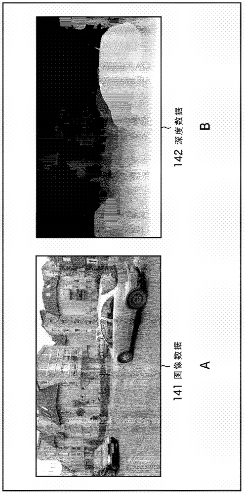
[0413] Figure 36 The image encoding device 500 is a device that receives a 3D image and encodes it. The depth data generation unit 511 of the image coding device 500 receives X camera images and X output images (521-1, 521-2, ... and 521-X), and compares the pictures at the same time point in these images in units of pixels , and generate the depth data 522 of the picture at this time point. The generated depth data can be represented by, for example, grayscale bitmap data, as the above reference figure 2 as described by B.

[0414] Regarding the method used by the depth data generation unit 511 to generate depth data, many research results from various...


PUM


Abstract

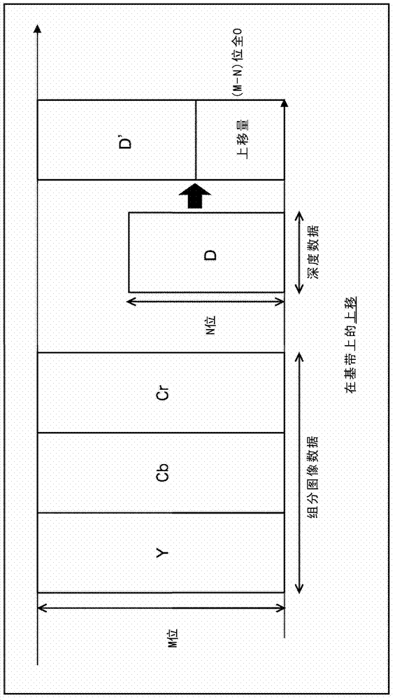
Disclosed are an image processor, an image processing method, and a program which can further improve encoding efficiency. In step S104, a bit shift unit (112) uses the bit depth of detected image data to shift depth data (D) acquired in step S103 and adjusts the bit depth of the depth data (D) to match the bit depth of the image data. In step S105, an encoder (113) encodes the image data and the depth data (D). In step S106, a rate controller (114) controls each encoding rate in step S105 in accordance with the encoding result for the image data and the depth data encoded in step S105. This curved surface is the prediction image. The method described can be applied to an image processor, for example.

Description

technical field [0001] The present invention relates to an image processing device, method, and program, and more particularly, to an image processing device, method, and program that can improve coding efficiency. Background technique [0002] Recently, stereoscopically viewable images (hereinafter referred to as 3D images) that can respond to so-called 3D (three-dimensional) have become increasingly popular. For example, the production of movies using stereoscopic 3D images is very active. 3D images are very different from traditional so-called 2D (two-dimensional) images that can only provide a flat perspective. Therefore, it is very useful to use this kind of 3D image for film production. [0003] In addition, video contents such as movies etc. using 3D images are efficiently compressed according to the MVC (Multi-View Video Coding) standard, which is like 2D images MPEG-4AVC extension format for video content. Also, the development of home appliances that can respon...

Claims


Application Information

Patent Timeline
Patent Type & Authority Applications(China)
IPC IPC(8): H04N13/02H04N7/26H04N7/30H04N13/00H04N19/00H04N19/147H04N19/34H04N19/463H04N19/503H04N19/593H04N19/597H04N19/60H04N19/61H04N19/63H04N19/70H04N19/85H04N19/86H04N19/91
CPCH04N19/00781H04N19/00278H04N13/0048H04N19/0006H04N7/26106H04N7/26563H04N7/26159H04N19/0009H04N19/00769H04N19/00545H04N13/0011H04N13/0059H04N19/00169H04N19/00842H04N2213/003H04N19/597H04N19/176H04N19/46H04N19/647H04N19/115H04N19/61H04N19/124H04N19/146H04N13/111H04N13/161H04N13/194H04N13/00
Inventor 福原隆浩
Owner SONY CORP
Learn More