
Heat recovery system for secondary reheating unit in power plant and power plant

A reheating system and secondary reheating technology, applied in chemical instruments and methods, liquid degassing, separation methods, etc., can solve the problems of increased design pressure of high-pressure heaters, increased lift of feed water pumps, inconvenience, etc., to achieve The effect of reducing design pressure, reducing engineering cost, and improving cycle efficiency

Active Publication Date: 2012-12-05
CHINA POWER ENG CONSULTING GRP CORP EAST CHINA ELECTRIC POWER DESIGN INST
View PDF5 Cites 7 Cited by
  • Summary
  • Abstract
  • Description
  • Claims
  • Application Information

AI Technical Summary

Problems solved by technology

[0003] With the continuous development of technology, the parameters of the double reheating unit are gradually increasing, and some shortcomings of the above-mentioned reheating system in the prior art are gradually revealed, which are mainly reflected in the following points: (1), with the main steam of the unit As the pressure increases gradually, the head of the feedwater pump in the system also gradually increases, so that the design pressure of the high pressure heater behind the feedwater pump also gradually increases
Taking the ultra-supercritical unit as an example, the design pressure of the high-pressure heater has reached 40-45MPa, which greatly increases the initial investment of the heater equipment; It is inconvenient for the high-pressure heater to be equipped with a drainage pump system that transports the steam-side drainage to the feed water, but the steam-side drainage of the high-pressure heater flows step by step, and finally drains to the deaerator, which is relatively low in efficiency of the thermal system

Method used


Image

  • Heat recovery system for secondary reheating unit in power plant and power plant
  • Heat recovery system for secondary reheating unit in power plant and power plant
  • Heat recovery system for secondary reheating unit in power plant and power plant

Examples


Embodiment Construction

[0031] Preferred embodiments of the present invention will be described in detail below with reference to the accompanying drawings, so as to better understand the purpose, features and advantages of the present invention. It should be understood that the embodiments shown in the drawings are not intended to limit the scope of the present invention, but only to illustrate the essence of the technical solutions of the present invention.

[0032] Hereinafter, main technical terms of the present invention will be described.

[0033] Secondary reheating unit: After the main steam from the boiler superheater does work in the high-pressure cylinder of the steam turbine, it is sent back to the primary reheater of the boiler for heating to increase the temperature, and then sent to the first medium-pressure cylinder of the steam turbine to continue to expand and work. Then send it back to the secondary reheater of the boiler for heating to increase the temperature, and then send it to...


PUM


Abstract

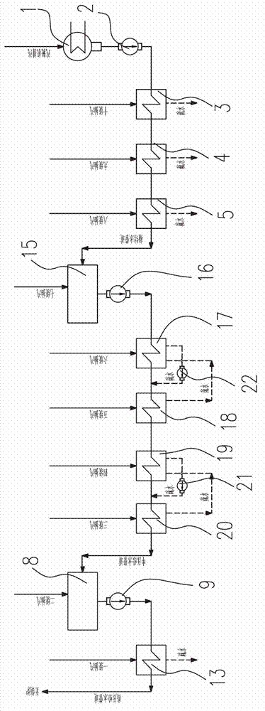
The invention provides a heat recovery system for a secondary reheating unit in a power plant and the power plant. The heat recovery system comprises a condenser, a condensate water pump, a low-pressure heater, a high-pressure water supply pump and a high-pressure heater, wherein both the low-pressure heater and the high-pressure heater are surface-type heaters. The heat recovery system is provided with more than two mixed heaters with different pressures; and one of the mixed heaters has a deoxidization function. The heat recovery system further comprises a medium-pressure heater and a medium-pressure water supply pump, wherein the medium-pressure heater and the medium-pressure water supply pump are arranged between any two mixed heaters. The heat recovery system has the benefits that the construction cost of equipment can be reduced, and meanwhile, the efficiency of a thermodynamic system is improved.

Description

technical field [0001] The invention relates to a power plant, in particular to a heat recovery system of a secondary reheat unit in the power plant. Background technique [0002] In the prior art, in the typical recuperation system of the double reheat unit, the steam turbine generally has 9 to 11 stages of steam extraction, which are respectively provided to 9 to 11 heaters, of which there is only one hybrid heater, and the hybrid heater At the same time, it has the function of deaeration, so this heater is usually called a deaerator, and the rest of the heaters are usually surface heaters. Typically, surface heaters after the condensate pump are called low-pressure heaters, and surface heaters after the feedwater pump are called high-pressure heaters. The hydrophobicity of surface type high pressure heaters is usually drained step by step to the next stage with lower pressure. The drainage of surface low-pressure heaters usually has the following two types: (1) Gradual ...

Claims


Application Information

Patent Timeline
Patent Type & Authority Applications(China)
IPC IPC(8): F22D1/50
Inventor 申松林叶勇健林磊
Owner CHINA POWER ENG CONSULTING GRP CORP EAST CHINA ELECTRIC POWER DESIGN INST
Learn More