Dismountable cake tray

A tray and cake technology, applied in the pastry holding device field, can solve the problems of taking up a lot of space, increasing transportation costs, inconvenient placement, etc., and achieve the effect of reducing the occupied space and making it easy to move

Inactive Publication Date: 2012-12-05
朱小龙
View PDF0 Cites 0 Cited by
  • Summary
  • Abstract
  • Description
  • Claims
  • Application Information

AI Technical Summary

Problems solved by technology

[0002] At present, the pastry trays on the market all adopt a one-piece structure and cannot be disassembled.
The result of this is that the pallet takes up too much space during transportation and is inconvenient to place, which greatly increases the transportation cost

Method used


Image

  • Dismountable cake tray
  • Dismountable cake tray

Examples


Embodiment Construction

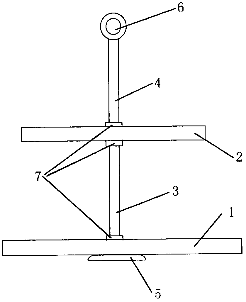
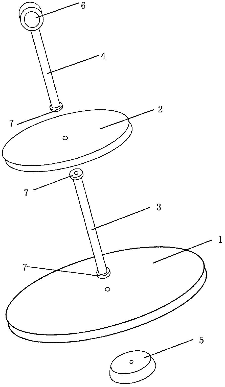
[0012] see figure 1 and figure 2 , a cake tray, its composition includes a first tray 1, a second tray 2, a first connecting rod 3, a second connecting rod 4, a handle 6, a base 5 and a rubber gasket 7. The tray is a circular glass plate with a through hole in the center; the connecting rod is hollow, and the inner wall of one end connected with the tray is provided with a thread, and the handle 6 is arranged on the top of the second connecting rod 4, and connected with the second connecting rod 4 connected as a whole; the center of the base 5 is also provided with a through hole. At the two ends of the first connecting rod 3 and the bottom end of the second connecting rod 4 , rubber gaskets 7 are also provided. During use, pass through the through hole of base 5 and first pallet 1 with screw, then be screwed with the bottom of first connecting rod 3; The bottom end of the top and the second connecting rod 4 is threaded.

[0013] The above are only preferred embodiments o...


PUM


Abstract

The invention discloses a dismountable cake tray which comprises a base and at least one tray part, and further comprises at least one hollow connecting rod, wherein through holes are formed in the base and the tray part respectively; screw threads are formed on the internal wall of the connecting rod; and the base, the tray part and the connecting rod are connected with one another through screws. The dismountable cake tray has the benefits that as the dismountable structure is adopted, plenty of space can be saved in transportation; and the dismountable cake tray is convenient in movement.

Description

technical field [0001] The invention relates to a cake holding device, in particular to a cake tray. Background technique [0002] At present, the trays for holding cakes on the market all adopt a one-piece structure and cannot be disassembled. The result of this is that the pallet takes up too much space during transportation and is inconvenient to place, which greatly increases the transportation cost. Contents of the invention [0003] The purpose of the present invention is to overcome the deficiencies of the prior art and provide a detachable cake tray. [0004] The technical solution adopted by the present invention is as follows: a detachable cake tray, including a base, a tray and a connecting rod, and the three are detachably connected. [0005] The base and the tray are respectively provided with through holes, the connecting rod is hollow, the inner wall is provided with threads, and the base, the tray and the connecting rod are connected by screws. [0006] ...

Claims


Application Information

Patent Timeline
Patent Type & Authority Applications(China)
IPC IPC(8): A47G21/04
Inventor 朱小龙
Owner 朱小龙
Why Eureka
Try Eureka