
Device connection method, electronic device and server

A technology for connecting electronic equipment and equipment, applied in the direction of electrical components, transmission systems, etc., can solve the problems of relative position identification between equipment, inconvenient use, unrealistic cost, etc.

Active Publication Date: 2016-06-01
LENOVO (BEIJING) LTD
View PDF6 Cites 0 Cited by
  • Summary
  • Abstract
  • Description
  • Claims
  • Application Information

AI Technical Summary

Problems solved by technology

[0003] Although the existing technology can realize convenient interconnection between devices, there are many ways to identify the location of the device, and each method has different limitations
For example, it is possible to locate a device through a network address on the Internet, but the accuracy of this positioning method is low
In addition, although the existing civilian GPS (Global Positioning System) has high accuracy, it cannot work indoors, nor can it realize the relative position identification between devices when the distance between the devices is very close (for example, less than 1 meter).
In every direction of the device, adding a sensor (infrared sensor / NFC, etc.) is neither realistic nor convenient to use in terms of cost.

Method used


Image

  • Device connection method, electronic device and server
  • Device connection method, electronic device and server
  • Device connection method, electronic device and server

Examples


no. 1 example

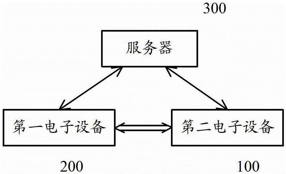
[0094] figure 1 is a block diagram showing the configuration of a system according to an embodiment of the present invention. Such as figure 1As shown, it is assumed that the system includes a server 300 and a first electronic device 200 and a second electronic device 100 . It should be noted that, for simplicity of description, only two electronic devices are shown in this system, but more electronic devices may be included according to user's needs. These electronic devices are within the predetermined range.

[0095] The first electronic device 200 and the second electronic device 100 can be any type of electronic device, as long as they can be interconnected in various ways, such as the Internet, base station network (such as 2G / 3G / 4G network, etc.), WiFi network, NFC wait. The electronic device may be, for example, a smart phone, a desktop computer, a notebook computer, a tablet computer, and the like.

[0096] In the present invention, it is assumed that the first e...

no. 2 example

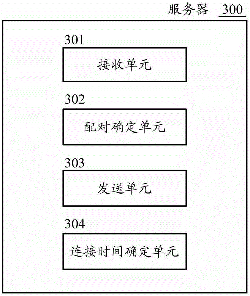
[0155] Refer below image 3 A server 300 according to an embodiment of the present invention is described. image 3 is a block diagram describing the functional configuration of the server 300 according to the embodiment of the present invention.

[0156] The server 300 according to the embodiment of the present invention includes:

[0157] The receiving unit 301 is configured to receive the first mutual identification information sent from the first electronic device and the second mutual identification information sent from the second electronic device;

[0158] The pairing determination unit 302 is configured to determine whether the first electronic device and the second electronic device are paired according to the first mutual identification information and the second mutual identification information;

[0159] The sending unit 303 is configured to send first communication connection establishment information to the first electronic device and second communication conn...

no. 3 example

[0172] Next, refer to Figure 4 A connection method according to an embodiment of the present invention is described. Figure 4 is a flowchart illustrating a connection method according to an embodiment of the present invention.

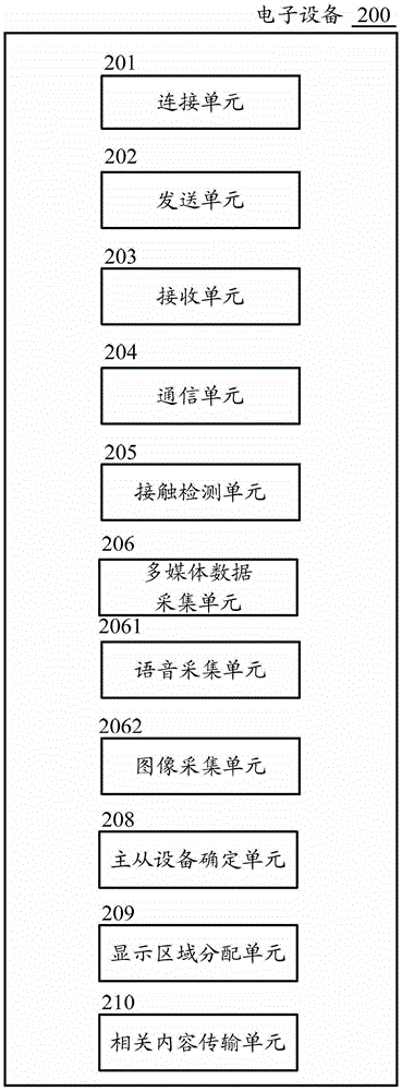
[0173] The connection method 400 according to the third embodiment of the present invention is applied to electronic equipment. The electronic device may be, for example, the aforementioned first electronic device 200 and second electronic device 100 . Here, the connection method is applied to the first electronic device 200 as an example for description. The connection method 400 includes:

[0174] Step S401: Start a connection operation with a second electronic device within a predetermined range of the first electronic device through a predetermined operation.

[0175] In this step, when a predetermined operation condition is met, a connection operation with the second electronic device 100 within a predetermined range of the first electronic ...


PUM


Abstract

A device connection method, electronic device and server based on multiple positioning are provided. The method is applied to a first electronic device, and the method includes: when a predetermined condition is met, initiating a connection operation with a second electronic device within a predetermined range of the first electronic device; converting the first mutual identification information Send to a server, where the server determines whether the first electronic device and the second electronic device are paired based on the first mutual identification information and the second mutual identification information sent from the second electronic device; When the server determines that the first electronic device and the second electronic device are paired according to the first mutual identification information and the second mutual identification information, the first communication connection establishment information sent from the server is received, wherein the The server also sends second communication connection establishment information to the second electronic device; and establishes a communication connection with the second electronic device according to the first and second communication connection establishment information.

Description

technical field [0001] The present application relates to electronic equipment, and in particular to a device connection method based on multiple positioning, electronic equipment and a server. Background technique [0002] With the popularity of mobile devices, short-distance interconnection between users has become an increasingly important application scenario. Users can establish connections in a temporarily constructed local area network without complicated settings, and realize rapid sharing of data and information. , has become a breakthrough point of innovation for operating systems and devices. [0003] Although the existing technology can realize convenient interconnection between devices, there are many ways to identify the location of the device, and each way has different limitations. For example, a device can be located through a network address on the Internet, but the accuracy of this positioning method is low. In addition, although the existing civilian GP...

Claims


Application Information

Patent Timeline
Patent Type & Authority Patents(China)
IPC IPC(8): H04L29/06
Inventor 于辰涛
Owner LENOVO (BEIJING) LTD
Learn More