


Quick Research
Generate reliable direction feasibility study reports for your R&D in just a few steps.

Technical Q&A
Discover and master advanced knowledge NOW. Basics, ideas, possibilities, all at once.

Find Solutions
As an expert in R&D theories, this can generate solutions to your technical problems instantly.

Evaluate Feasibility
Analyze your overall solution with one click, know your potential R&D risks in advance.

Monitor Landscape
Get weekly tech updates, stay abreast of the latest tech innovations and key insights.
Drive having an emergency closing function
A driver and emergency technology, applied in the direction of fluid-driven clutches, magnetic-driven clutches, non-mechanical-driven clutches, etc., can solve problems such as costs and achieve the effect of reducing costs
- Summary
- Abstract
- Description
- Claims
- Application Information
AI Technical Summary
Problems solved by technology
Method used
Image

Examples
Embodiment Construction
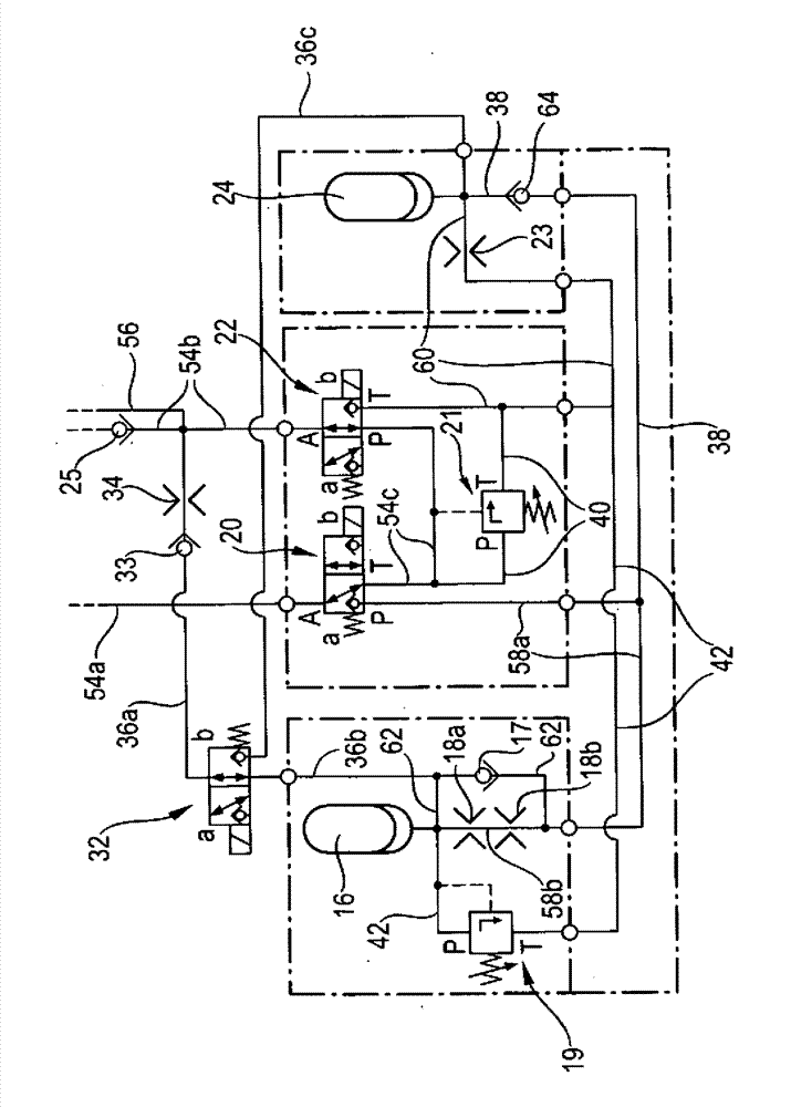
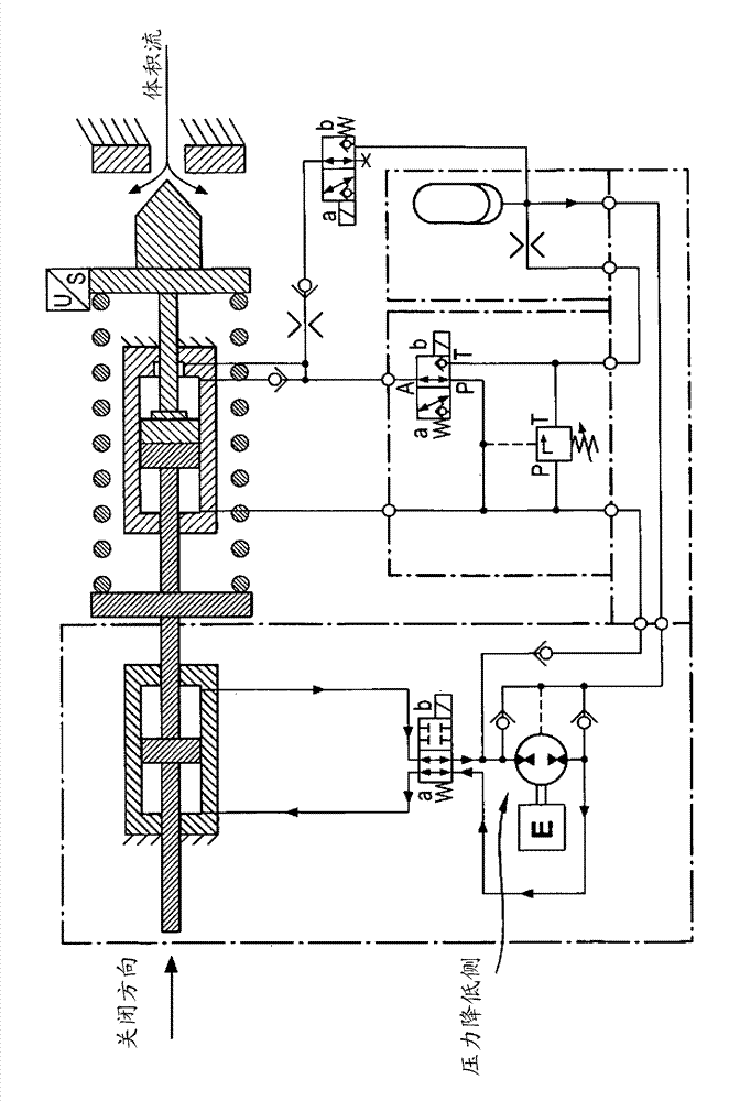
[0049] figure 1 A schematic diagram showing a first embodiment of a complete drive according to the invention is shown. The drive has an actuating drive 44 designed as an electric cylinder, by means of which the seat valve (in the figure 1 in) of valve body 2 to the right in the closing direction or (in figure 1 center) moves to the left in the opening direction.
[0050] figure 1 The open position of the seat valve 1 , 2 is shown, from which position the valve body 2 of the seat valve can be pressed against the valve seat 1 of the seat valve in the closing direction.
[0051] Furthermore, the drive has a hydraulic system 48 by means of which the drive according to the invention can be switched, in particular from normal operation to emergency operation. In normal operation the valve body 2 is moved by the adjustment drive 44 and in emergency operation alternatively by the emergency spring 6 integrated into the clutch device 46 .
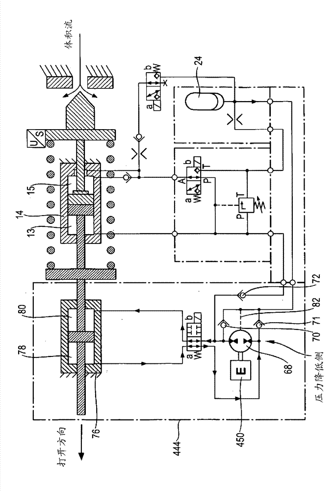
[0052] figure 2 show according to fig...
PUM
 Abstract
Description
Claims
Application Information
 - R&D Engineer
- R&D Manager
- IP Professional
- Industry Leading Data Capabilities
- Powerful AI technology
- Patent DNA Extraction
Browse by: Latest US Patents, China's latest patents, Technical Efficacy Thesaurus, Application Domain, Technology Topic, Popular Technical Reports.
© 2024 PatSnap. All rights reserved.Legal|Privacy policy|Modern Slavery Act Transparency Statement|Sitemap|About US| Contact US: help@patsnap.com