
Field emission electron device

An electronic device, field emission technology, applied in electrical components, cathode ray tubes/electron beam tubes, circuits, etc., can solve the problems of poor brightness and low electron emission efficiency of field emission display devices, and achieve high field emission current, high effect of brightness

Active Publication Date: 2015-03-11
TSINGHUA UNIV +1
View PDF4 Cites 0 Cited by
  • Summary
  • Abstract
  • Description
  • Claims
  • Application Information

AI Technical Summary

Problems solved by technology

[0004] However, in the above-mentioned field emission display device, since each pixel unit only includes a cathode electrode and an anode electrode spaced apart, the electron emission efficiency of the field emission display device is relatively low, thereby making the field emission display device brightness poor

Method used


Image

  • Field emission electron device
  • Field emission electron device
  • Field emission electron device

Examples


Embodiment Construction

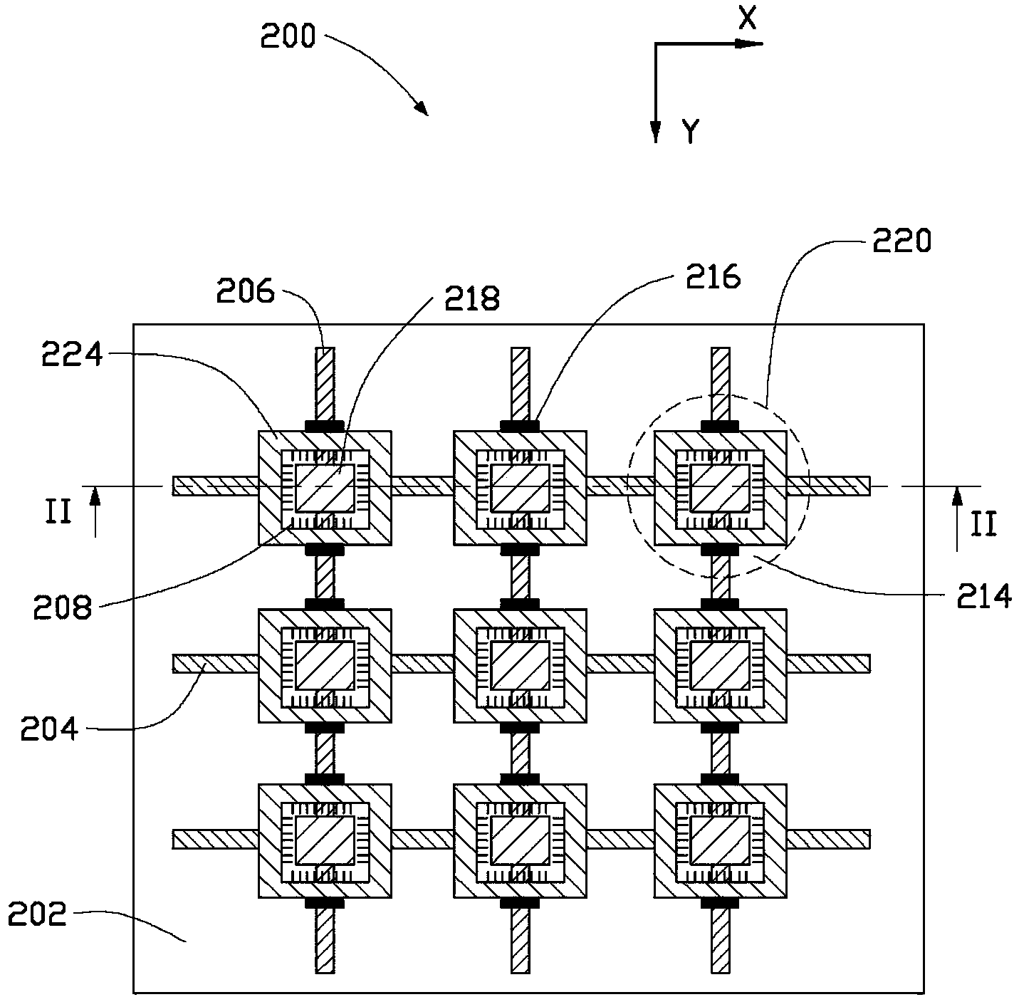
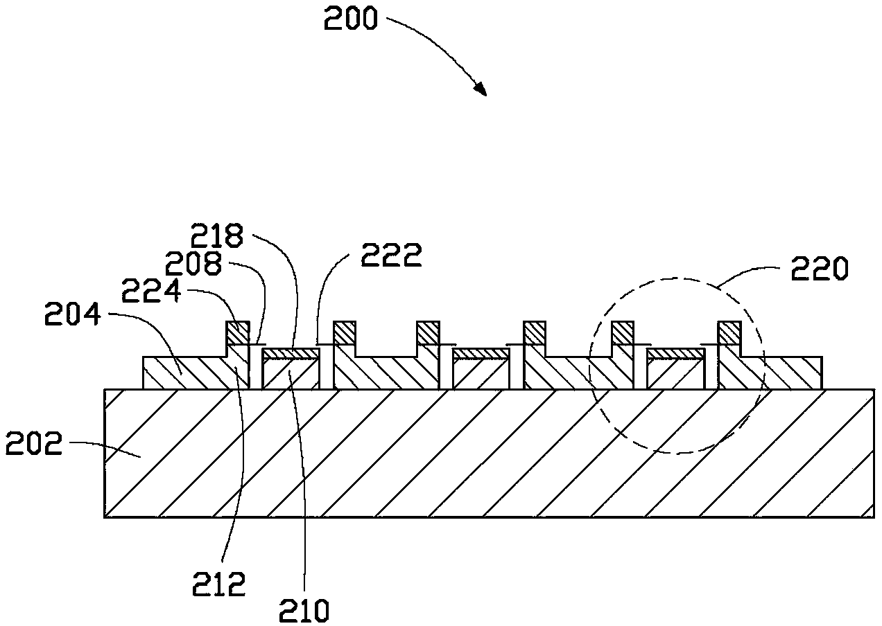
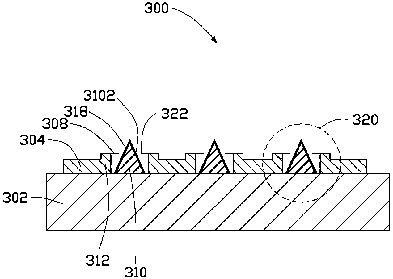
[0034] The field emission electronic device and the field emission display device of the present invention will be further described in detail below in conjunction with the accompanying drawings. It can be understood that the field emission electronic device and the field emission display device may include a plurality of pixel units, and the drawings of the embodiments of the present invention only give some pixel units as examples for illustration.

[0035] see figure 1 , figure 2 The first embodiment of the present invention provides a field emission display device 200 , which includes an insulating substrate 202 , a plurality of pixel units 220 , and a plurality of row electrode leads 204 and a plurality of column electrode leads 206 .

[0036] The plurality of row electrode leads 204 and the plurality of column electrode leads 206 are respectively disposed on the surface of the insulating substrate 202 in parallel and at intervals. Preferably, the plurality of row elec...


PUM


Abstract

The invention provides a field emission electron device, which comprises an insulating base with a surface, multiple line electrode leads and multiple row electrode leads that are all arranged on the surface of the insulating base in parallel and at intervals, and multiple electron emission units arranged on the surface of the insulating base, wherein the multiple line electrode leads and the multiple row electrode leads mutually intersect to set and define multiple intersection points in an electric insulating manner, and each electron emission unit corresponds to one of the intersection points. Each electron emission unit further includes a second electrode electrically connected with the corresponding row electrode lead, a first electrode arranged at an interval with the second electrode and arranged in a manner of partially surrounding the second electrode at least, and multiple electron emission bodies arranged on the surface (far away from the insulating base) of at least one of the first electrode and the second electrode, wherein the first electrode is electrically connected with the corresponding line electrode lead.

Description

technical field [0001] The invention relates to a field emission electronic device, in particular to a planar field emission electronic device. Background technique [0002] Field emission electronic devices work at low temperature or room temperature, and have the advantages of low power consumption, fast response and low outgassing compared with thermal electron emission devices. Field emission electronic devices have a wide range of applications in field emission display devices. [0003] A field emission display device in the prior art includes an insulating substrate, a plurality of pixel units, and a plurality of row electrode leads and a plurality of column electrode leads. Wherein, the plurality of row electrode leads and the plurality of column electrode leads are arranged on the surface of the insulating substrate in parallel and at equal intervals. The plurality of row electrode leads and the plurality of column electrode leads are arranged to cross each other, ...

Claims


Application Information

Patent Timeline
Patent Type & Authority Patents(China)
IPC IPC(8): H01J31/12H01J29/02
Inventor 柳鹏范守善
Owner TSINGHUA UNIV
Learn More