
Manual pressing structure for double-rotation paint mixing machine

A compacting structure and mixer technology, applied to mixers with rotating containers, mixers, mixer accessories, etc., can solve problems such as inconvenient, dangerous machine operation, and inability for users to operate the machine, so as to achieve safe and reliable structure , the effect of convenient operation

Active Publication Date: 2012-11-07
ZHENGZHOU SANHUA TECH & IND
View PDF4 Cites 7 Cited by
  • Summary
  • Abstract
  • Description
  • Claims
  • Application Information

AI Technical Summary

Problems solved by technology

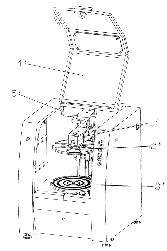
[0005] In the prior art, the manual compression type double-rotary mixer is compressed by such as figure 1 The shown compression handle is used for operation or other similar compression handles are directly used for compression operation at this position. When the compression operation is required, it is required to maintain a certain operating space above the top cover of the machine, that is, The upper top cover of the machine should be able to be opened, so that the user can operate and turn the pressing handle with both hands to realize the pressing and opening of the upper platen and the lower platen. Generally, the space of the paint mixing store is compact, which is not very convenient for these users. If the user forgets to take off the handle, there will be a certain danger when the machine is running. Moreover, the separate pressing handle is easy to lose, which makes the user unable to operate the machine.

Method used


Image

  • Manual pressing structure for double-rotation paint mixing machine
  • Manual pressing structure for double-rotation paint mixing machine
  • Manual pressing structure for double-rotation paint mixing machine

Examples


Embodiment Construction

[0036] The present invention is further described below in conjunction with accompanying drawing:

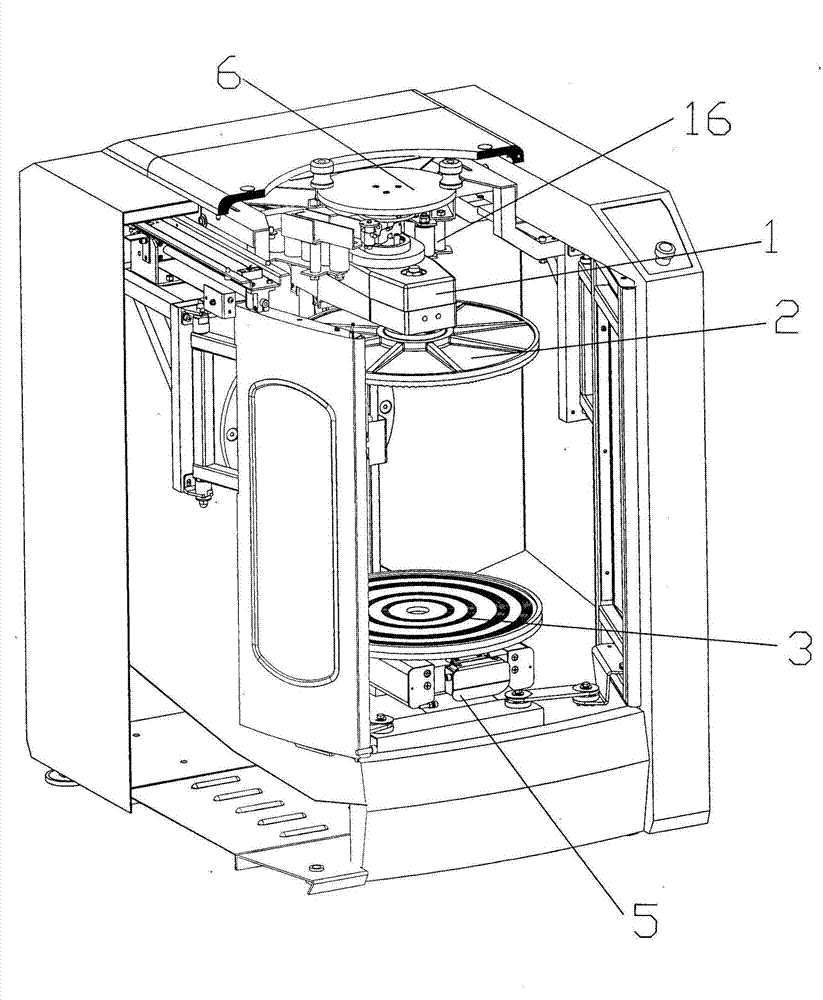
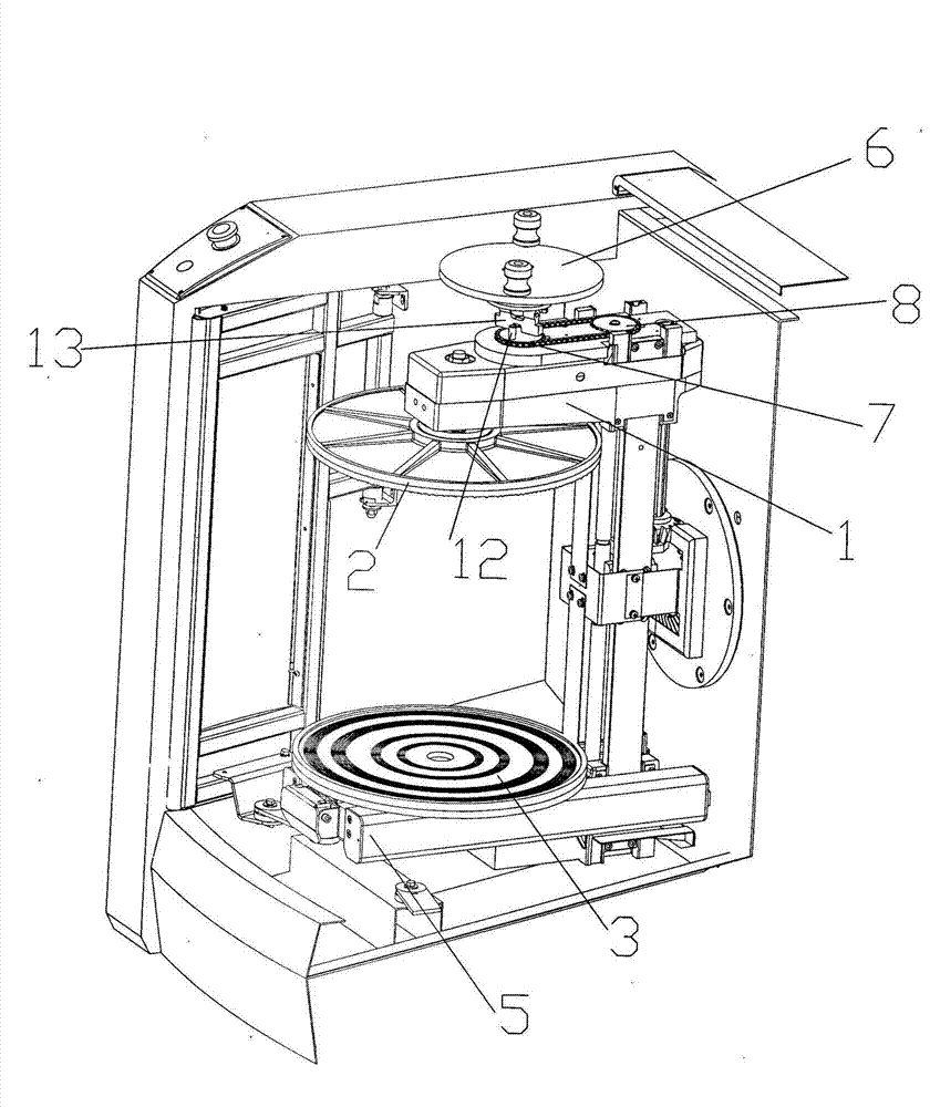
[0037] Such as Figure 2-11 Shown: the present invention is applicable to the manual pressing structure of double-rotating paint mixer, is that the manual rotating pressing assembly is installed in the top cover 4 of the mixing machine, and described manual rotating pressing assembly includes pressing The compact disc 6, the rotating shaft seat 10 and the compact disc rotating shaft 9 worn in the rotary shaft seat, the top of the compact disc rotating shaft 9 is fixedly connected with the compact disc 6, and a compact shift fork is installed at the lower end of the compact disc rotating shaft 9, The pressing driving wheel 7 of the mixer is provided with a dialed part suitable for overlapping with the pressing fork; after the machine completes the rotation and mixing of the paint, the support arm slowly stops rotating, and there is Brake mechanism makes the vertical position tha...


PUM


Abstract

The invention relates to a manual pressing structure for a double-rotation paint mixing machine, which is characterized in that: the upper top cover of the mixing machine is internally provided with a manual rotating pressing component, the pressing component comprises pressing discs, a rotating shaft base, rotating shafts of the pressing discs, the rotating shafts of the pressing discs penetrate through the rotating shaft base, the top ends of the rotating shafts of the pressing discs are fixedly connected with the pressing discs, the lower ends of the rotating shafts of the pressing discs are provided with pressing shifting components, pressing driving wheels are provided with shifted components which are in overlap joint with the shifting components, and when the upper top cover is fully opened, the pressing driving wheels match with the rotating shafts of the pressing discs coaxially. By pushing and pulling the upper top cover, the shifting connecting matching structures can be combined and separated smoothly, and by rotating the pressing discs to drive the pressing driving belt wheels to rotate, the upper pressing disc and the lower pressing disc can move oppositely, thus a colored paint barrel can be pressed and opened without using a special separable pressing wrench. The manual pressing structure is convenient to use and is safe and reliable in structure.

Description

[0001] technical field [0002] The invention relates to a double-rotating mixer for paint, paint and the like, in particular to a double-rotating paint mixer for manually pressing color paint buckets. Background technique [0003] At present, double-rotating mixers in the paint industry are divided into automatic compacting double-rotating mixers and manual compacting double-rotating mixers. The present invention relates to a manual compacting double-rotating mixer. Double-rotary mixer is a kind of equipment for mixing or mixing paint, paint and the like, which can make the bucket containing paint, paint and the like (hereinafter referred to as the paint bucket in this manual) The mixer rotates around the geometric centerline of the paint barrel and at the same time rotates around the rotation axis perpendicular to the geometric centerline of the barrel, that is, it rotates and revolves at the same time to achieve the purpose of double-rotation mixing of paint. When it is ...

Claims


Application Information

Patent Timeline
IPC IPC(8): B01F9/00B01F15/00
Inventor 石建勋薛耀斌袁福明
Owner ZHENGZHOU SANHUA TECH & IND
Learn More