Method, system and device for locating abnormal ONU in passive optical network system

A passive optical network and positioning method technology, applied in the field of abnormal optical network unit positioning methods, systems and devices, can solve problems affecting normal ONU work, reducing network service quality, etc., to reduce the positioning range and improve network services quality, effect of reducing impact

Inactive Publication Date: 2012-10-17
ZTE CORP
View PDF3 Cites 9 Cited by
  • Summary
  • Abstract
  • Description
  • Claims
  • Application Information

AI Technical Summary

Problems solved by technology

[0011] In view of this, the embodiments of the present invention provide a method, system and device for locating an abnormal ONU in a passive optical network system, to solve the problem of affecting the work of a normal ONU and reducing the quality of network service in the existing abnormal ONU locating

Method used


Image

  • Method, system and device for locating abnormal ONU in passive optical network system
  • Method, system and device for locating abnormal ONU in passive optical network system
  • Method, system and device for locating abnormal ONU in passive optical network system

Examples


Embodiment Construction

[0020] In order to make the technical problems, technical solutions and beneficial effects to be solved by the present invention clearer and clearer, the present invention will be further described in detail below in conjunction with the accompanying drawings and embodiments. It should be understood that the specific embodiments described here are only used to explain the present invention, not to limit the present invention.

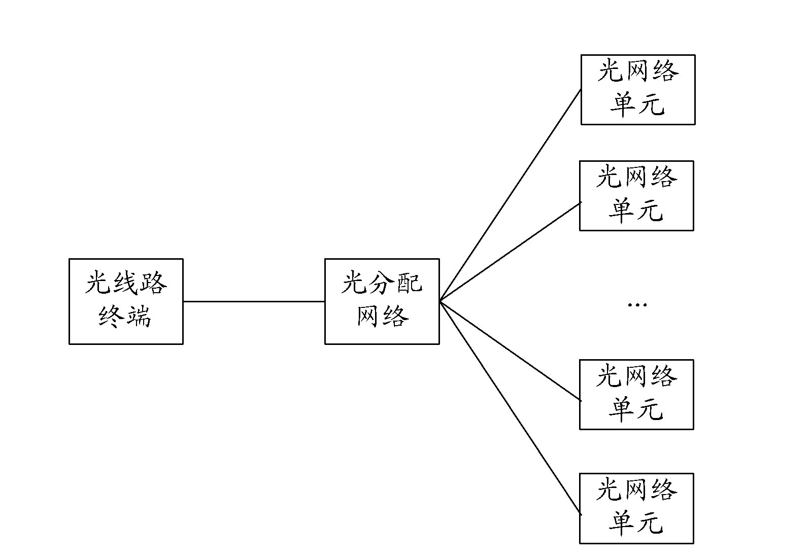
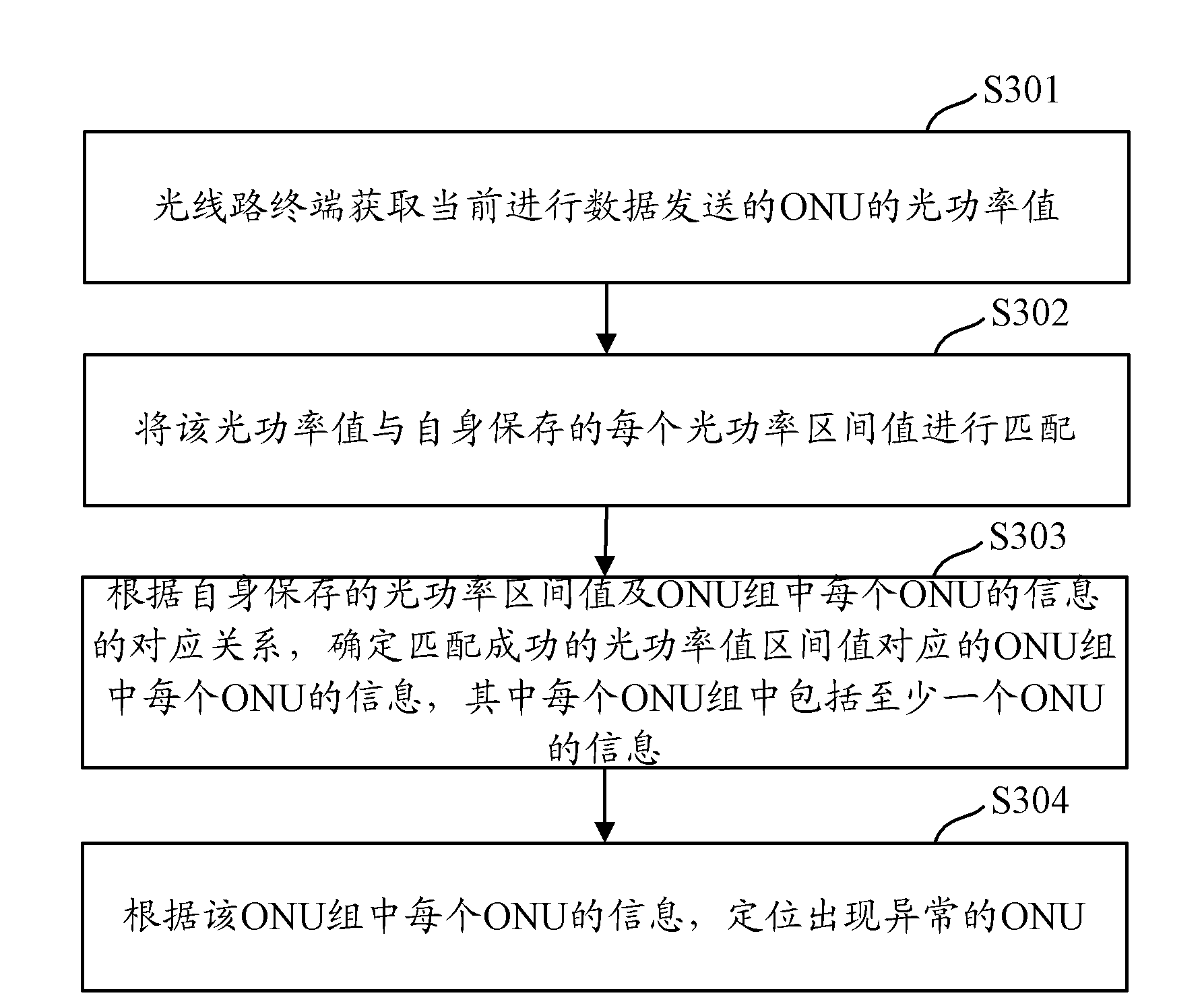
[0021] In order to reduce the impact on ONUs that work normally in the system and improve network service quality, the embodiments of the present invention provide a method, system, and device for locating abnormal ONUs in a PON system. Since the optical power values ​​of each ONU are different, the The ONUs in the system are combined arbitrarily to form different ONU groups. Each group of ONUs includes at least one ONU, and saves the optical power interval value of the ONU group. When there are abnormal ONUs, determine the optical power values ​​of seve...


PUM


Abstract

The invention discloses a method, a system and a device for locating an abnormal ONU in a passive optical network system. In the method, according to different optical power values of each ONU, ONUs in the system are combined randomly to compose different ONU groups, and optical power interval values of the ONU groups are stored. When an abnormal ONU exists, an ONU optical power value of current transmitting data is acquired and is matched with the stored optical power interval values, to determine a corresponding ONU group where the abnormal ONU locates and to locate the abnormal ONU in the ONU group. Because the ONU group comprises limited ONUs, location range of the abnormal ONU is narrowed down, thereby decreasing influences on other normal ONUs and improving the quality of network services.

Description

technical field [0001] The present invention relates to the field of communication technology, in particular to a positioning method, system and device for an abnormal optical network unit (Optical Network Unit, ONU) in a passive optical network (Passive Optical Network, PON) system. Background technique [0002] With the development of network technology, a large number of voice, data, video and other services are transmitted through the network, so the requirements for bandwidth are constantly increasing. In order to meet this demand, the PON system was produced. [0003] figure 1 It is a schematic diagram of the topology structure of the PON system. The PON system adopts a point-to-multipoint network structure. The PON system includes an optical line terminal (optical line terminal, OLT) on the network side, and an optical distribution network (Optical Distribution Node, OLT) on the user side. ODN) and Optical Network Unit (Optical Network Unit, ONU), where the ODN provi...

Claims


Application Information

Patent Timeline
IPC IPC(8): H04B10/08
Inventor 耿丹张伟良
Owner ZTE CORP
Why Eureka
Try Eureka