Quick clamping mechanism

A technology of quick clamp and output shaft, which is applied in the directions of motor tools, portable motor devices, manufacturing tools, etc., can solve problems such as inconvenience of operation, and achieve the effect of ingenious structure

Inactive Publication Date: 2012-10-17
NANJING CHERVON IND
View PDF5 Cites 6 Cited by
  • Summary
  • Abstract
  • Description
  • Claims
  • Application Information

AI Technical Summary

Problems solved by technology

In the existing rotating power tools, since the working accessories need to be rotated, spherical bodies are often used to lock the working accessories. Usually, there is a circle of locking grooves in the circumferential direction of the working accessories, and the spherical bodies are used for fixing by intruding into the anvil. The chamber of the working accessory cooperates with the locking groove to realize locking. The existing clamping mechanism for controlling the locking or unlocking of the spherical body often requires the use of two hands at the same time for work. However, in actual work engineering, it is often only possible to Free up one hand to operate, so it causes great inconvenience to the operation

Method used


Image

  • Quick clamping mechanism
  • Quick clamping mechanism
  • Quick clamping mechanism

Examples


Embodiment Construction

[0029] Below in conjunction with accompanying drawing and specific embodiment, promptly take electric screwdriver as example, the present invention is made concrete introduction.

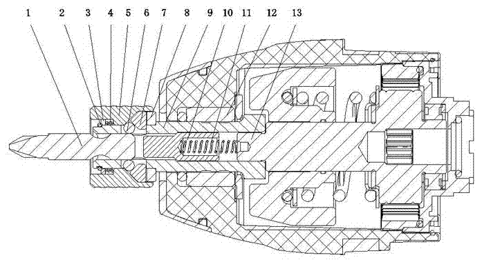
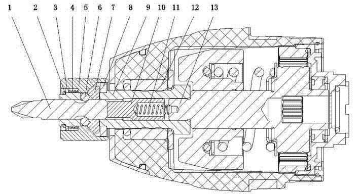
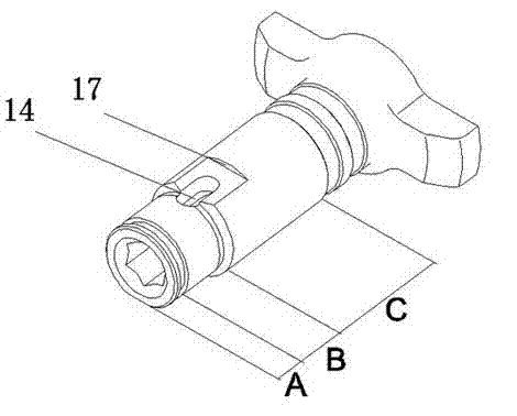
[0030] refer to Figure 1 to Figure 5 As shown, a quick clamping mechanism of the present invention mainly includes: a locking member 6 , a movable member 7 , an anvil 9 , and a bushing 5 .

[0031] Wherein, the locking piece 6 is used to cooperate with the locking groove 18 of the working attachment 1. Preferably, the locking piece 6 can be made of metal material in order to ensure the structural strength. The center of hammer anvil 9 is provided with a placement cavity, and the effect of placement cavity is to insert the working accessory 1 and accommodate the slide pin 10. The placement cavity can be designed as a through cavity with both ends connected or as a cavity with one end open. The hammer anvil 9 is used for inserting One end of the working accessory 1 is figure 1 The left end shown is...


PUM


Abstract

The invention discloses a quick clamping mechanism. The quick clamping mechanism comprises an output shaft which is used for mounting a tool accessory and forms a locking slotted hole which passes through the internal wall of the output shaft, a locking component arranged in the locking slotted hole, a bushing block sleeved on the output shaft, and a first energy storing component acted on the bushing block; the quick clamping mechanism further comprises a moving component arranged in the locking slotted hole; and the moving component is in contact with the bushing block, and can exert radial component force and axial component force to the bushing block when the tool accessory is inserted. The quick clamping mechanism has the advantages of ingenuity in structure, convenience in achievement, and capability of effectively achieving the operation of clamping or unlocking a working accessory through one hand; and the quick clamping mechanism brings great convenience to a user for use.

Description

technical field [0001] The invention is applicable to a quick clip mechanism. Background technique [0002] In rotary electric tools, it is often necessary to replace working accessories with corresponding specifications or functions according to specific applications. For example, electric screwdrivers need to replace corresponding heads for different screw specifications. In the existing rotating power tools, since the working accessories need to be rotated, spherical bodies are often used to lock the working accessories. Usually, there is a circle of locking grooves in the circumferential direction of the working accessories, and the spherical bodies are used for fixing by intruding into the anvil. The chamber of the working accessory cooperates with the locking groove to realize locking. The existing clamping mechanism for controlling the locking or unlocking of the spherical body often requires the use of two hands at the same time for work. However, in actual work engi...

Claims


Application Information

Patent Timeline
Patent Type & Authority Applications(China)
IPC IPC(8): B25F5/00B25B21/00
Inventor 周红陶
Owner NANJING CHERVON IND
Why Eureka
Try Eureka