Glass cleaning device
A technology of cleaning glass and relative position, applied in cleaning equipment, household appliances, applications, etc., can solve the problems of difficult control of distance adjustment, complex adjustment mechanism, and difficult control of magnetic force changes.
- Summary
- Abstract
- Description
- Claims
- Application Information
AI Technical Summary
Problems solved by technology
Method used
Image
Examples
Embodiment 1
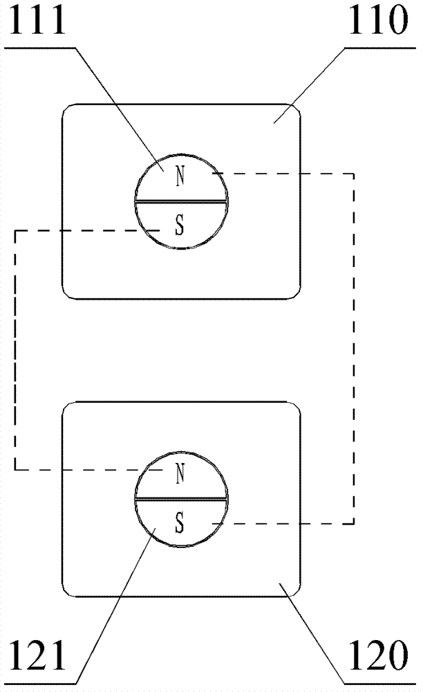
[0056] figure 2 It is a schematic structural diagram of a glass-wiping device according to an embodiment of the present invention, as figure 2As shown, the glass-wiping device includes a master 110 and a slave 120 . The host 110 is provided with a first magnet part, and the slave 120 is provided with a second magnet part. Through the magnetic attraction between the first magnet part and the second magnet part, the host 110 and the slave 120 are mutually attracted to the glass 2 and the slave machine 120 can follow up with the master machine 110 under the action of the attraction force of the first magnet part and the second magnet part. In addition, the magnetic force between the first magnet part and the second magnet part can be changed by operating the movable member. The slave machine 120 is provided with a work piece (not shown in the figure), and the work piece may be any cleaning tool such as a scraper, flannelette, or scouring pad.
[0057] In this embodiment, the...
Embodiment 2
[0067] Figure 4 It is a schematic structural diagram of the second embodiment of the glass-wiping device of the present invention. Such as Figure 4 As shown, the difference between this embodiment and Embodiment 1 is that the master 210 also includes a third magnet part 212, and the slave 220 includes a fourth magnet part 222; the third magnet part 212 is fixed in the master 210, and the fourth magnet part 222 is fixed in the slave machine 220. The third magnet part 212 and the fourth magnet part 222 are disposed corresponding to each other, and the polarities of the magnets opposite to each other are opposite.
[0068] Figure 5A It is a schematic structural diagram of the second embodiment of the present invention when the glass-wiping device is at the maximum magnetic attraction. Such as Figure 5A and refer to Figure 4 As shown, the third magnet part 212 provided on the host machine 210 and the fourth magnet part 222 provided on the slave machine 220 generate an a...
Embodiment 3
[0073] Figure 6A It is a schematic diagram of the structure of the third glass-wiping device in the embodiment of the present invention when it is in the maximum magnetic force, as shown in Figure 6A As shown, the difference between the present embodiment and the second embodiment is that the third magnet part 312 includes a third magnet I312a and a third magnet II312b, and the fourth magnet part 322 includes a fourth magnet I322a and a fourth magnet II322b. The third magnet I312a and the third magnet II312b are arranged corresponding to the fourth magnet I322a and the fourth magnet II322b respectively, and attract each other.
[0074] In this embodiment, by adding a fixed magnet, the suction force is greater, and the device is more securely attached. Specifically, the third magnet part 312 provided on the master machine 310 and the fourth magnet part 322 provided on the slave machine 320 generate an attractive force between them, and the attractive force generated by a sin...
PUM
 Abstract
Description
Claims
Application Information
 - R&D
- Intellectual Property
- Life Sciences
- Materials
- Tech Scout
- Unparalleled Data Quality
- Higher Quality Content
- 60% Fewer Hallucinations
Browse by: Latest US Patents, China's latest patents, Technical Efficacy Thesaurus, Application Domain, Technology Topic, Popular Technical Reports.
© 2025 PatSnap. All rights reserved.Legal|Privacy policy|Modern Slavery Act Transparency Statement|Sitemap|About US| Contact US: help@patsnap.com


