
Motion predicting or compensating method

A technology of motion prediction and motion vector, which is applied in the field of communication, can solve the problems of insufficient accuracy and high search complexity, and achieve the effect of maintaining complexity, improving coding performance, and reasonable complexity

Active Publication Date: 2015-05-06
HUAWEI TECH CO LTD
View PDF4 Cites 0 Cited by
  • Summary
  • Abstract
  • Description
  • Claims
  • Application Information

AI Technical Summary

Problems solved by technology

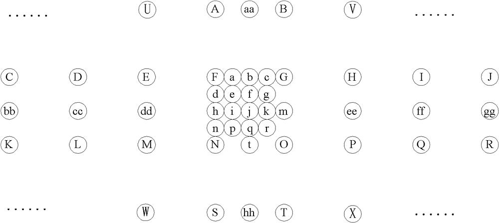
[0005] Since the accuracy of motion prediction and compensation can reach non-integer pixel positions, in the motion prediction or compensation process at the codec side, when selecting the optimal motion vector, it is necessary to search for a large number of candidate motion vector pointing positions, and select the optimal one from them. Motion vectors are used for prediction and compensation. Since the candidate motion vectors are the motion information of image blocks related to the temporal and spatial domains around the current encoding or decoding block, these motion vectors are not accurate enough when used as the current block motion vector, but they can be re-do pixel-level motion The search complexity is too high, so how to improve the encoding performance of existing schemes while maintaining a reasonable complexity becomes a key issue

Method used


Image

  • Motion predicting or compensating method
  • Motion predicting or compensating method
  • Motion predicting or compensating method

Examples


Embodiment 1

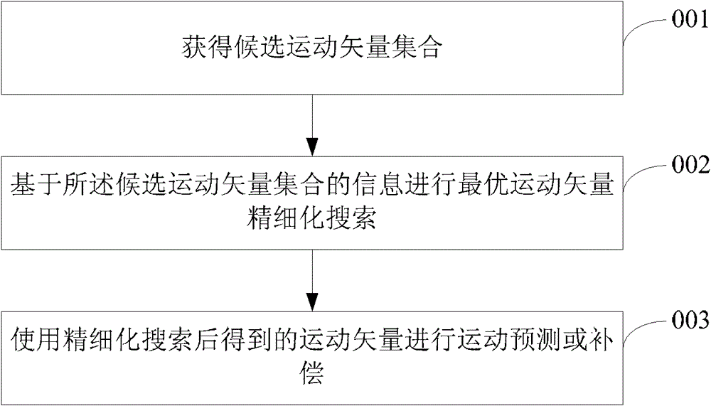
[0022] like figure 2 It is shown that an embodiment of the present invention provides a motion prediction or compensation method, including:

[0023] Step 001. Obtain a set of candidate motion vectors.

[0024] In this embodiment of the present invention, the set of candidate motion vectors may be different sets of motion vectors.

[0025] In some implementation manners, the set of candidate motion vectors may be a first set of motion vectors, and the first set of motion vectors is generated using motion vectors related to at least one item of time domain and space domain of the currently encoded or decoded block.

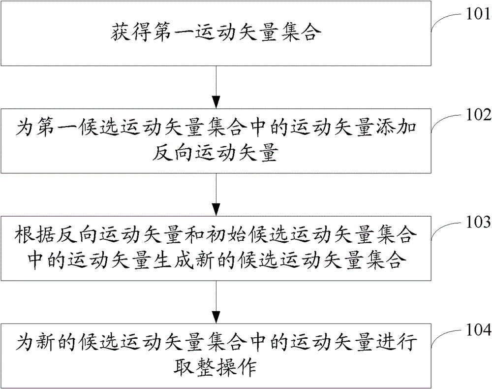
[0026] In some implementations, the set of candidate motion vectors may be a second set of motion vectors, and the obtaining the set of candidate motion vectors includes: generating an initial A set of motion vectors; negate the motion vectors in the initial set of motion vectors to obtain an inverted motion vector; the inverted motion vectors and the initial se...

Embodiment 2

[0042] Embodiment two: see Figure 3A , the method for generating the candidate motion vector set in Embodiment 1 is further described as follows:

[0043]Step 101: Obtain a first set of motion vectors, the first set of motion vectors is generated using motion vectors related to at least one item of time domain and space domain of a currently encoded or decoded block. That is, the initial candidate motion vector set of the current encoding block or decoding block is acquired.

[0044] Specifically, the spatial candidate motion vector is obtained according to the surrounding coding block or decoding block of the current coding block or decoding block, and the time domain candidate motion vector of the current coding block or decoding block is obtained according to the reference frame, which can be the current coding block or decoding block. In the previous frame, or the next frame, or the previous frame and the next frame of the current frame where the block is located, the sp...


PUM


Abstract

Embodiments of the present invention provide a motion prediction or compensation method during a video coding and decoding process. A motion prediction or compensation method provided in the embodiments of the present invention includes: acquiring a candidate motion vector set; conducting a refined search for an optimal motion vector based on information of the candidate motion vector set; and performing motion prediction or compensation by using the motion vector acquired by the refined search. This improves coding performance and meanwhile maintains reasonable complexity.

Description

technical field [0001] The invention relates to the field of communication technology, in particular to a motion prediction or compensation method in video coding and decoding. Background technique [0002] Motion prediction and motion compensation are important technologies in video compression. Part of the bits in the video compression code stream are used to transmit motion vector information, especially in the case of low bit rates. The bits usually exceed 50% of the total bits of the code stream. Therefore, it is necessary to improve coding efficiency by selecting an optimal motion vector. For the video coding of continuous dynamic images, several consecutive images are divided into three types: P, B, and I. For P frames, the prediction is made according to the correlation between this frame and the adjacent previous frame (I frame or P frame) To compress the data of this frame; for the B frame, it is to predict and compress the current frame according to the correlat...

Claims


Application Information

Patent Timeline
Patent Type & Authority Patents(China)
IPC IPC(8): H04N19/513H04N19/56
CPCH04N19/533H04N19/52H04N19/523H04N19/56
Inventor 林四新杨名远周建同于浩平
Owner HUAWEI TECH CO LTD
Learn More