Combined push clamp duplex spring type magnetic latching relay

A technology of magnetic latching relays and push cards, applied in the direction of electromagnetic relays, electromagnetic relay details, relays, etc., to achieve the effects of reasonable structure, high synchronization, and high working reliability

Active Publication Date: 2012-10-03
SANYOU CORP LTD
View PDF5 Cites 3 Cited by
  • Summary
  • Abstract
  • Description
  • Claims
  • Application Information

AI Technical Summary

Problems solved by technology

[0003] At present, magnetic latching relays are divided into armature direct-acting magnetic latching relays and armature rotating magnetic latching relays according to the different armature action methods. There is still room for further improvement in terms of improving work reliability and synchronization

Method used


Image

  • Combined push clamp duplex spring type magnetic latching relay
  • Combined push clamp duplex spring type magnetic latching relay
  • Combined push clamp duplex spring type magnetic latching relay

Examples


Embodiment Construction

[0018] Below in conjunction with accompanying drawing, the present invention will be described in further detail:

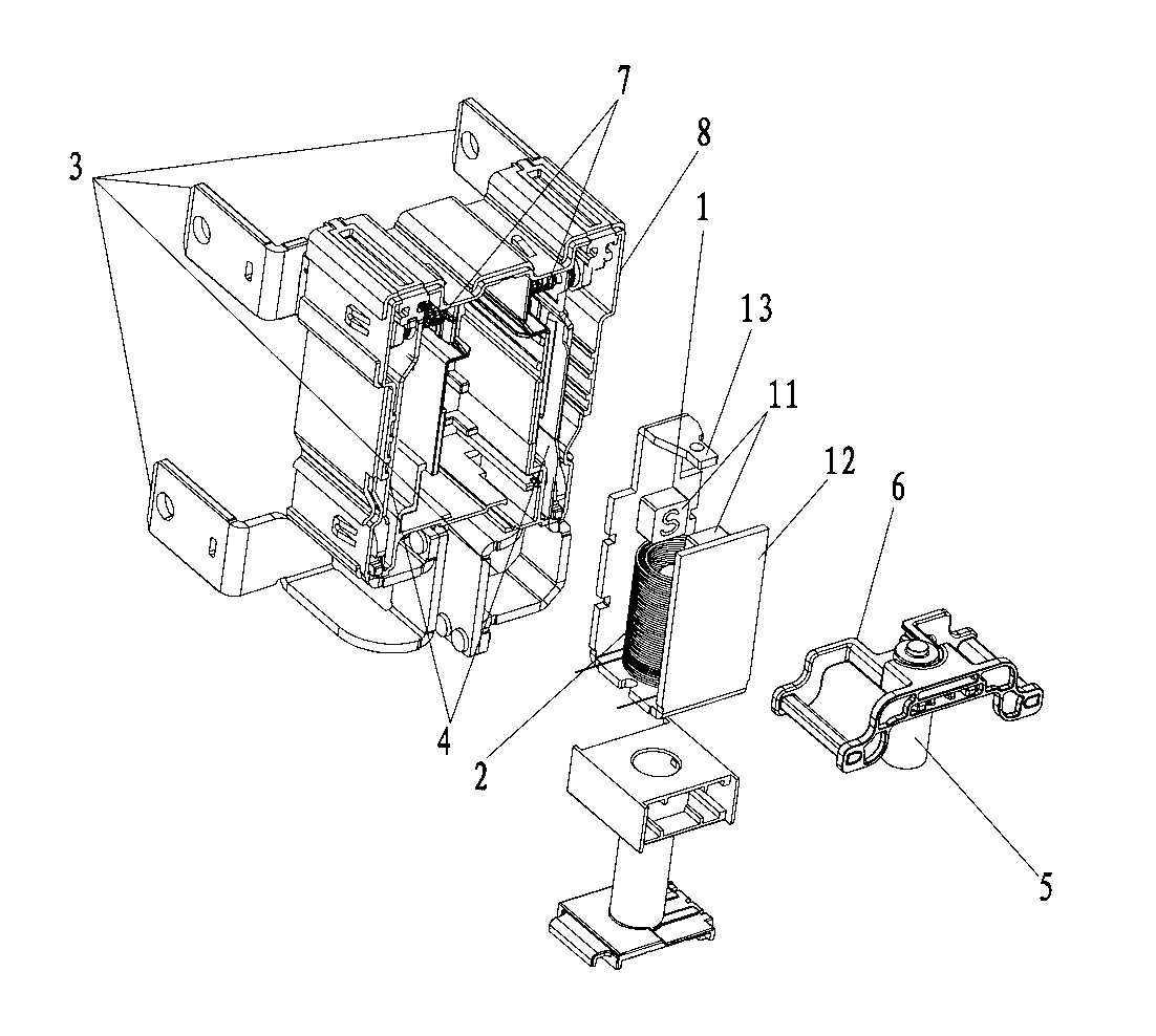
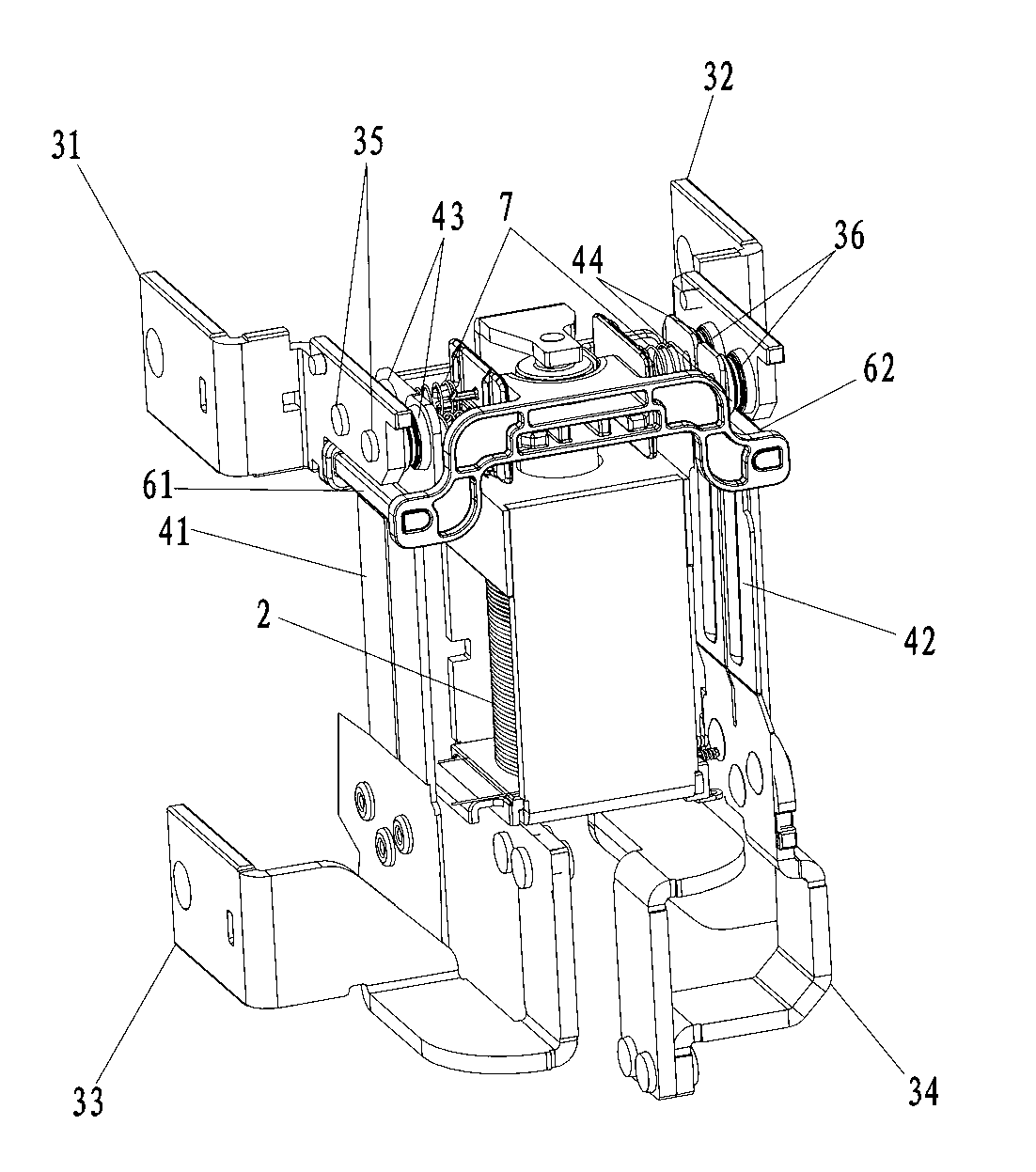
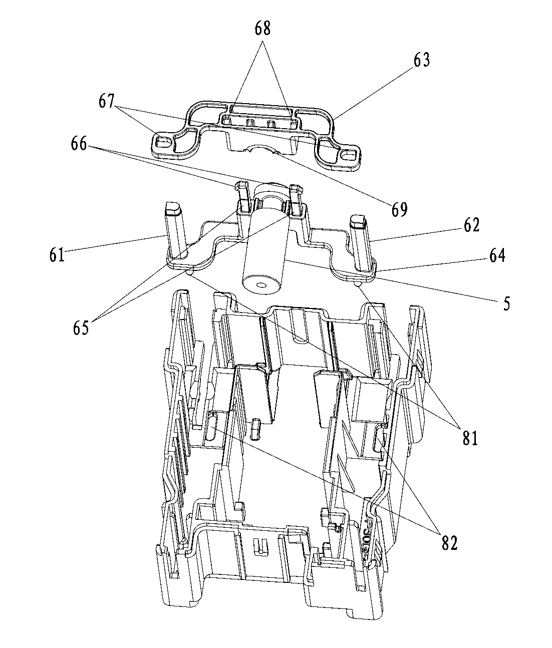
[0019] see figure 1 , 2 , the present invention is a combined push card dual spring magnetic latching relay, including a permanent magnet assembly 1, a coil assembly 2, a lead sheet set 3, a moving reed set 4, an armature 5 and a housing 8, and the permanent magnet assembly 1 includes two A permanent magnet 11 and a yoke 12, the two permanent magnets 11 are located at the front and rear relative positions on the upper part of the coil assembly 2, the yoke 12 is located outside the coil assembly 2, and a yoke end 13 protrudes above the coil assembly 2; The upper left lead-out piece 31, the upper right lead-out piece 32, the lower left lead-out piece 33 and the lower right lead-out piece 34 respectively located at the four corners of the permanent magnet assembly 1 are composed of two left static contacts 35 on the upper left lead-out piece 31, the upper right lea...


PUM


Abstract

The invention discloses a combined push clamp duplex spring type magnetic latching relay. The combined push clamp duplex spring type magnetic latching relay comprises a permanent magnet assembly, a coil assembly, a lead-out sheet group, a movable spring sheet group, an armature and a shell, wherein the permanent magnet assembly comprises two permanent magnets and a piece of yoke iron; the two permanent magnets are positioned on the upper part of the coil assembly and are opposite to each other; the piece of yoke iron is positioned outside the coil assembly; a yoke iron end extends out of the upper part of the coil assembly; the lead-out sheet group consists of an upper left lead-out sheet, an upper right lead-out sheet, a left lower lead-out sheet and a right lower lead-out sheet which are positioned at four corners of the permanent magnet assembly respectively; the upper left lead-out sheet is provided with two left static contacts; and the upper right lead-out sheet is provided with two right static contacts. The combined push clamp duplex spring type magnetic latching relay is novel and reasonable in structure, convenient to assemble and high in working reliability, the left and right movable spring sheets are high in action synchronism, and the movable and static contacts are stable in contact state or separation state.

Description

technical field [0001] The invention relates to a magnetic latching relay, in particular to a dual-spring type magnetic latching relay with a combined pushing card. Background technique [0002] Magnetic latching relay, the closed or open state is only held by the magnetic force generated by the permanent magnet, and the transition between the closed and open states depends on a certain width of positive DC or reverse DC pulse voltage to excite the coil to trigger the action of the linkage parts And completed an electrical control device. The magnetic latching relay has the characteristics of only pulse excitation, low power consumption, strong load, safety and reliability, etc., and is widely used in automatic control circuits, especially in high-current power systems. [0003] At present, magnetic latching relays are divided into armature direct-acting magnetic latching relays and armature rotating magnetic latching relays according to the different armature action method...

Claims


Application Information

Patent Timeline
Patent Type & Authority Applications(China)
IPC IPC(8): H01H51/01H01H50/58
Inventor 宋朝阳
Owner SANYOU CORP LTD
Why Eureka
Try Eureka