
Backlight module

A backlight module, light source technology, applied in optics, light guides, light sources, etc., can solve problems such as unfavorable brightness performance

Inactive Publication Date: 2012-09-26
AU OPTRONICS CORP
View PDF4 Cites 7 Cited by
  • Summary
  • Abstract
  • Description
  • Claims
  • Application Information

AI Technical Summary

Problems solved by technology

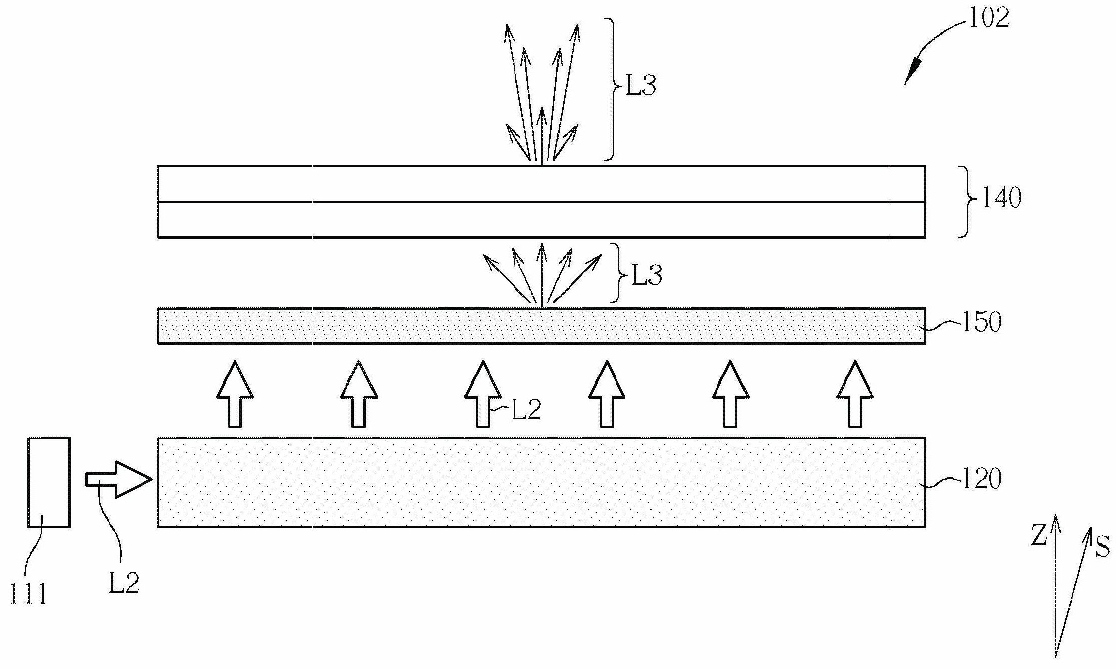
Therefore, when the excitation light L3 is emitted through the brightness enhancement film 140 of the conventional backlight design, the brightness of the excitation light L3 in the vertical projection direction Z will be smaller than the brightness in the side viewing direction S, which is not conducive to the brightness performance in the normal front viewing direction.

Method used


Image

  • Backlight module
  • Backlight module
  • Backlight module

Examples


Embodiment Construction

[0041] In order to enable those who are familiar with the technical field of the present invention to further understand the present invention, the preferred embodiments of the present invention are enumerated below, together with the accompanying drawings, to describe in detail the composition of the present invention and the desired effects .

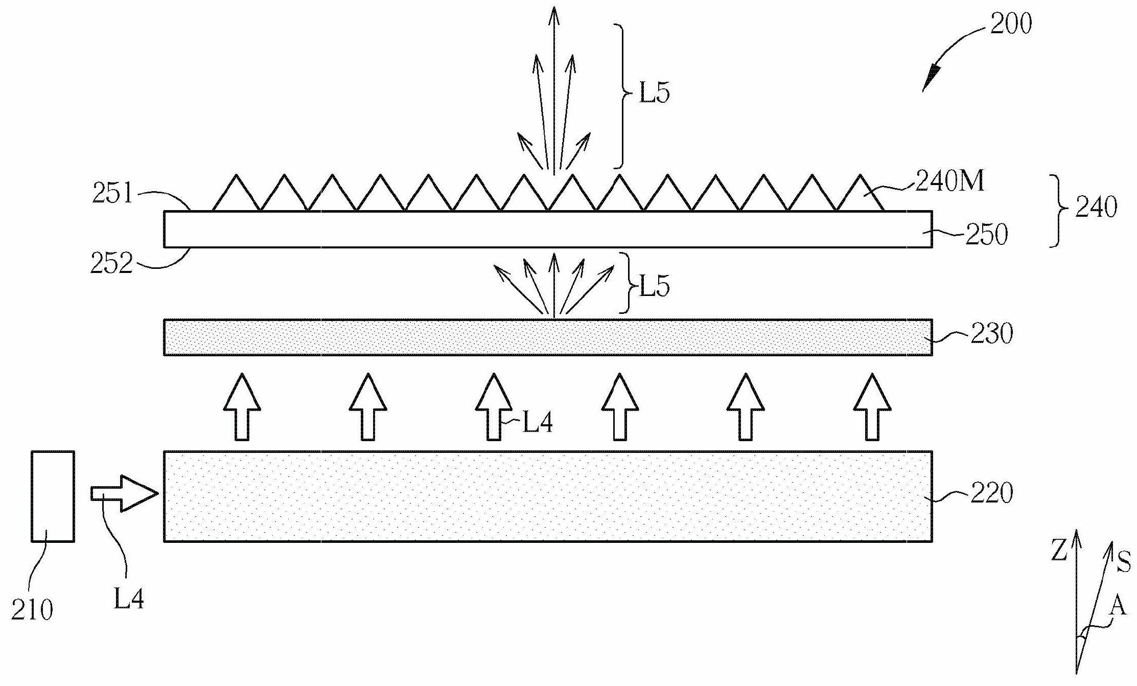
[0042] Please refer to Figure 3 to Figure 6 . Figure 3 to Figure 6 A schematic diagram of a backlight module according to a first preferred embodiment of the present invention is shown. in image 3 is a side view diagram, Figure 4 is a partially enlarged schematic diagram of the optical film of the backlight module, Figure 5 and Figure 6 It is a schematic top view of the optical film of the backlight module. For the convenience of description, the drawings of the present invention are only schematic diagrams for easier understanding of the present invention, and the detailed proportions thereof can be adjusted according to ...


PUM


Abstract

A backlight module comprises a light source, a photoluminescence layer and an optical film. The light source is used for providing light; the photoluminescence layer is used for generating excitated light through the radiation of the light provided by the light source; and the optical film and the photoluminescence layer are overlapped at the same vertical projection direction. The optical film comprises a substrate and a plurality of two-dimensional symmetrical micro-structures which are arranged on at least one surface of the substrate, and the excitated light is emitted through the two-dimensional symmetrical micro-structures.

Description

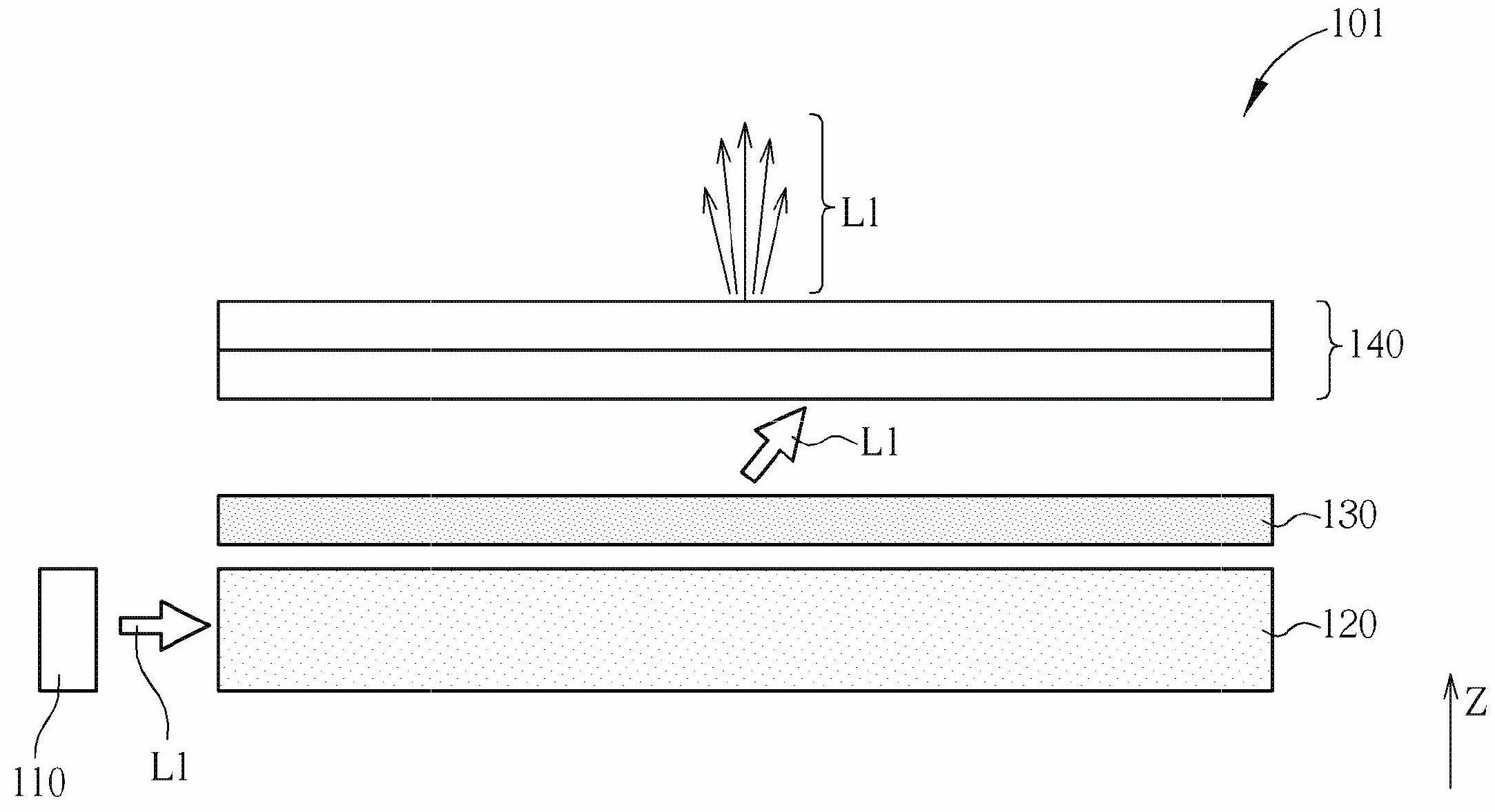
【Technical field】 [0001] The invention relates to a backlight module, in particular to a backlight module which uses a photoluminescent layer to emit light and uses an optical film to improve light distribution. 【Background technique】 [0002] Due to the advantages of low power consumption, long component life, low driving voltage, and fast response, light-emitting diodes have been widely used in traffic signs, decorative lamps, and light sources for various electronic products. Backlight modules made of light emitting diodes have also been used in many flat panel display products. [0003] Please refer to figure 1 and figure 2 . figure 1 and figure 2 The prior art backlight module 101 and backlight module 102 are shown respectively. Such as figure 1 As shown, the prior art backlight module 101 includes a light source 110 , a light guide plate 120 , a diffusion plate 130 and a brightness enhancement film 140 . The backlight module 101 belongs to the edge type backli...

Claims


Application Information

Patent Timeline
IPC IPC(8): F21S8/00F21V13/00
CPCF21V13/02G02B5/0231F21Y2105/00F21S8/00G02B6/0001G02B5/0278G02F1/133F21V2008/006F21V2200/20G02B6/0053G02F1/133606G02F1/133617
Inventor 张译文范富诚
Owner AU OPTRONICS CORP
Learn More