
Magnetic suspension elevator guiding system and control method thereof

A guiding system and magnetic levitation technology, applied in elevators, transportation and packaging, etc., can solve the problems of poor accuracy and stability, large power loss, etc., and achieve the effect of eliminating friction, reducing energy consumption, and reducing the accuracy of guide rails

Inactive Publication Date: 2012-09-26
SHENYANG POLYTECHNIC UNIV
View PDF7 Cites 19 Cited by
  • Summary
  • Abstract
  • Description
  • Claims
  • Application Information

AI Technical Summary

Benefits of technology

This patented technical solution allows an improved movement mechanism that does away from any direct physical connection during operation while still maintaining stable performance over longer periods of use. It uses magnetism instead of traditional methods like roller guides or slide rails to prevent wear on both components and enhance their lifespan. By monitoring these factors accurately and controllably, this design ensures smooth motion even when there may have issues such as slippage or misalignment caused by uneven surfaces.

Problems solved by technology

The technical problem addressed in this patented text relates to reducing linear movement component's impact on their performance due to its interaction with other moving elements during operation. This can cause damage such as wearing away from certain points along the path that they move over time.

Method used


Image

  • Magnetic suspension elevator guiding system and control method thereof
  • Magnetic suspension elevator guiding system and control method thereof
  • Magnetic suspension elevator guiding system and control method thereof

Examples


Embodiment approach

[0035] Implementation method: Below in conjunction with accompanying drawing, the present invention is further described:

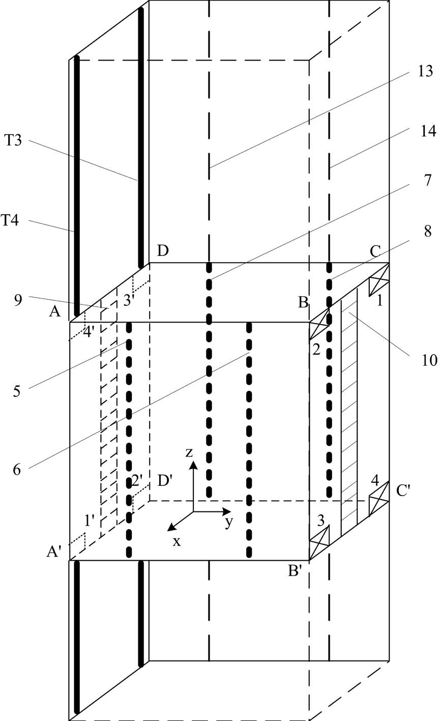
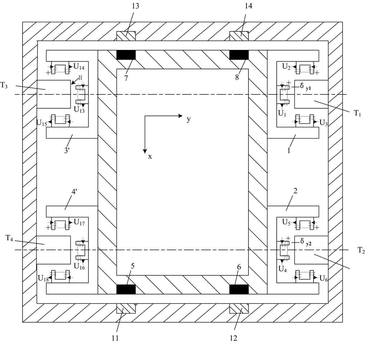
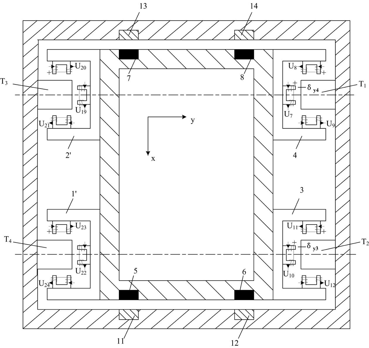
[0036] Such as figure 1 and 4 As shown, the present invention provides a magnetic levitation elevator guide system, including an elevator car and an elevator shaft, and a guide device is arranged on the left and right side walls of the elevator shaft, the guide device is a single electromagnetic guide device, and the guide device includes a The guide rail on the elevator shaft wall and the U-shaped guide shoe 111 arranged on the outer wall of the elevator car, the U-shaped guide shoe corresponds to the guide rail, and the guide rail is a T-shaped magnetic guide rail; the three inner walls of the U-shaped guide shoe are also provided with The U-shaped electromagnetic force device corresponds to the guide rail and maintains a gap with the guide rail; the U-shaped electromagnetic force device is a U-shaped iron core wound with an electromagnetic coil.

...


PUM


Abstract

The invention provides a magnetic suspension elevator guiding system, comprising an elevator car and an elevator shaft. The magnetic suspension elevator guiding system is characterized in that a guiding device is arranged at each of right and left side walls of the elevator shaft; the guiding device comprises a guide rail which is arranged on an elevator shaft wall and a U-shaped guide shoe which is arranged on an outer wall of the elevator car; the U-shaped guide shoe corresponds to the guide rail; a U-shaped electromagnetic force device is further arranged on three inner walls of the U-shaped guide shoe; the U-shaped electromagnetic force device corresponds to the guide rail, and a gap is arranged between the U-shaped electromagnetic force device and the guide rail; and the U-shaped electromagnetic force device is a U-shaped iron core wound with an electromagnetic coil. The invention also provides a control method for the overall elevator car. Meanwhile, an electric-driven system (EDS) and electromagnetic system (EMS) mixed suspension system is introduced, the energy consumption is reduced, the running cost of an elevator is lowered, the requirement of the system on the guide rail precision is reduced, and the overall optimization is easily realized.

Description


Claims


Application Information

Patent Timeline
Owner SHENYANG POLYTECHNIC UNIV
Learn More