
Pipe handling system and method for handling pipe

A technology for pipe fittings and supply systems, applied in the directions of pipe laying and maintenance, pipe/pipe joints/pipe fittings, drilling pipes, etc., can solve the problem of large size of the arm, and achieve the effect of increased safety

Active Publication Date: 2015-11-25
ITREC BV
View PDF5 Cites 0 Cited by
  • Summary
  • Abstract
  • Description
  • Claims
  • Application Information

AI Technical Summary

Problems solved by technology

A disadvantage of the known systems and methods is that the higher the tube placement tower, the larger the arm size needs to be

Method used


Image

  • Pipe handling system and method for handling pipe
  • Pipe handling system and method for handling pipe
  • Pipe handling system and method for handling pipe

Examples


Embodiment Construction

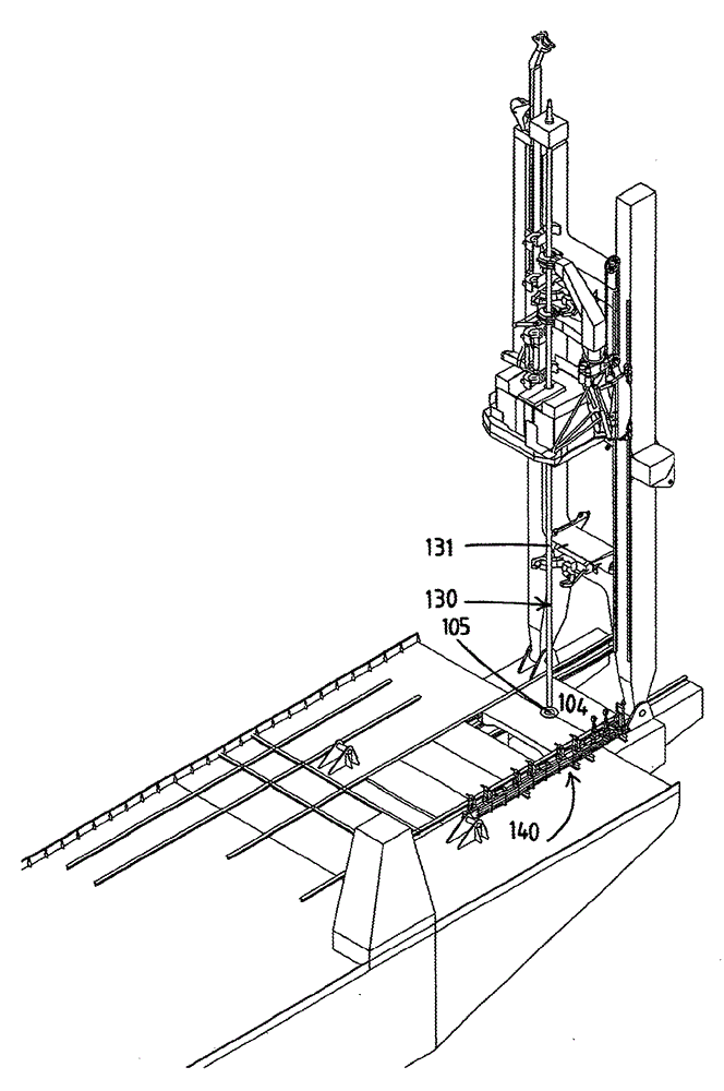
[0038] exist figure 1 In , a pipe handling system 1 according to the invention is shown. The pipe handling system 1 includes a stand 20 for supporting the tower 10 . Column 10 is in this embodiment a line delivery column 10, which will be described in more detail below. Tower 10 allows pipelines (and other objects as will be explained) to be dropped through a moon pool (not shown) or alongside stand 20 .

[0039] Here, the tower is positioned on the end side of the support 20 , for example possibly on the stern side of the ship. In alternative arrangements, the tower 10 may be arranged, for example, on the port side of the ship or on the starboard side of the ship, or in the mid-section of the ship.

[0040] In another not shown embodiment, the tower may be in the form of a derrick (eg a lattice frame) extending over the moonpool, with a working line or tubular launching track passing within the derrick structure.

[0041]The lower end of the tower 10 is supported on the s...


PUM


Abstract

The present invention relates to a tubular handling system (1) comprising:—a tower (10) comprising a tubular lift device for lowering and / or raising a tubular in an essentially vertical orientation,—a support (20) for supporting the tubular-laying tower—a tubulars supply system, preferably provided on the support, for supplying tubulars to an essentially horizontal supply position in the vicinity of the tower,—a tubular handling apparatus (2) for transporting a tubular between the essentially horizontal supply position and the tubular lift device in the tower, wherein the tubular handling apparatus comprises: a gripper (4a, 4b) adapted for gripping the tubular, a base (6), and a boom (5) to which the one or more grippers are attached, which boom is pivotable with respect to the base in a boom. According to the invention, the tubular handling apparatus further comprises a vertical extending frame (7), wherein said base is guided by said frame and movable in a vertical translational movement with respect to the frame.

Description

technical field [0001] The invention relates to a pipe handling system, comprising: [0002] - a tower comprising pipe lifting means for lowering and / or raising pipes in a substantially vertical orientation, [0003] - supports for supporting the pipe fittings on the tower, [0004] - a pipe supply system, preferably arranged on a support, for supplying pipes to a substantially horizontal supply location near the tower, [0005] - pipe handling equipment for transferring pipe between the substantially horizontal supply location and the pipe lifting device of the tower, wherein the pipe handling equipment includes: [0006] - grabbers suitable for grabbing pipes, [0007] - base, [0008] - an arm to which one or more grippers are attached, the arm being able to move relative to the base in the arm pivot direction about a horizontal arm pivot axis in a lowered position for gripping a pipe in said substantially horizontal supply position and with Pivots between a raised pos...

Claims


Application Information

Patent Timeline
Patent Type & Authority Patents(China)
IPC IPC(8): F16L1/19F16L1/20E21B19/15E21B19/22
CPCF16L1/19E21B19/155F16L1/203F16L1/207
Inventor R.L.W.诺文斯T.W.A.维梅杰J.鲁登堡
Owner ITREC BV
Learn More