
Measurement method and measurement instrument of revolution body part

A technology of measuring instruments and rotators, applied to measuring devices, instruments, optical devices, etc., can solve the problems of unrealization, adjustment errors, and inability to ensure the overall level of the workbench, etc., and achieve the effect of convenient adjustment and fast speed

Inactive Publication Date: 2014-11-05
HENAN UNIV OF SCI & TECH
View PDF5 Cites 0 Cited by
  • Summary
  • Abstract
  • Description
  • Claims
  • Application Information

AI Technical Summary

Problems solved by technology

For non-contact optical measuring equipment, since the sample will move in the vertical direction during the adjustment process, adjustment errors will inevitably be introduced, resulting in low adjustment accuracy
Leveling in the one-dimensional direction cannot guarantee the overall level of the workbench; at the same time, for the rotating parts to be measured, the measuring instrument that requires the axis of rotation to be placed in a vertical state cannot be realized by the above-mentioned adjustment workbench.

Method used


Image

  • Measurement method and measurement instrument of revolution body part
  • Measurement method and measurement instrument of revolution body part
  • Measurement method and measurement instrument of revolution body part

Examples


Embodiment Construction

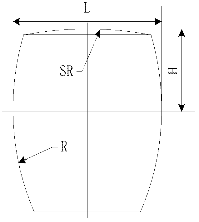
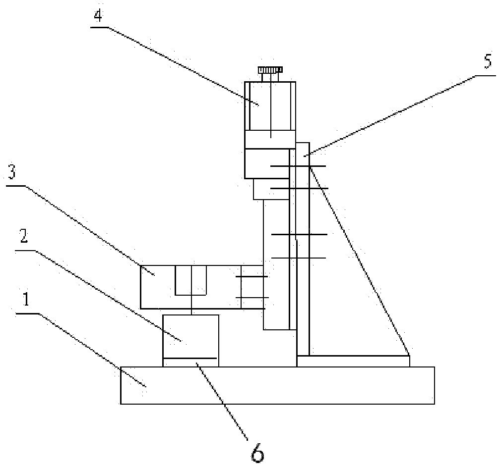
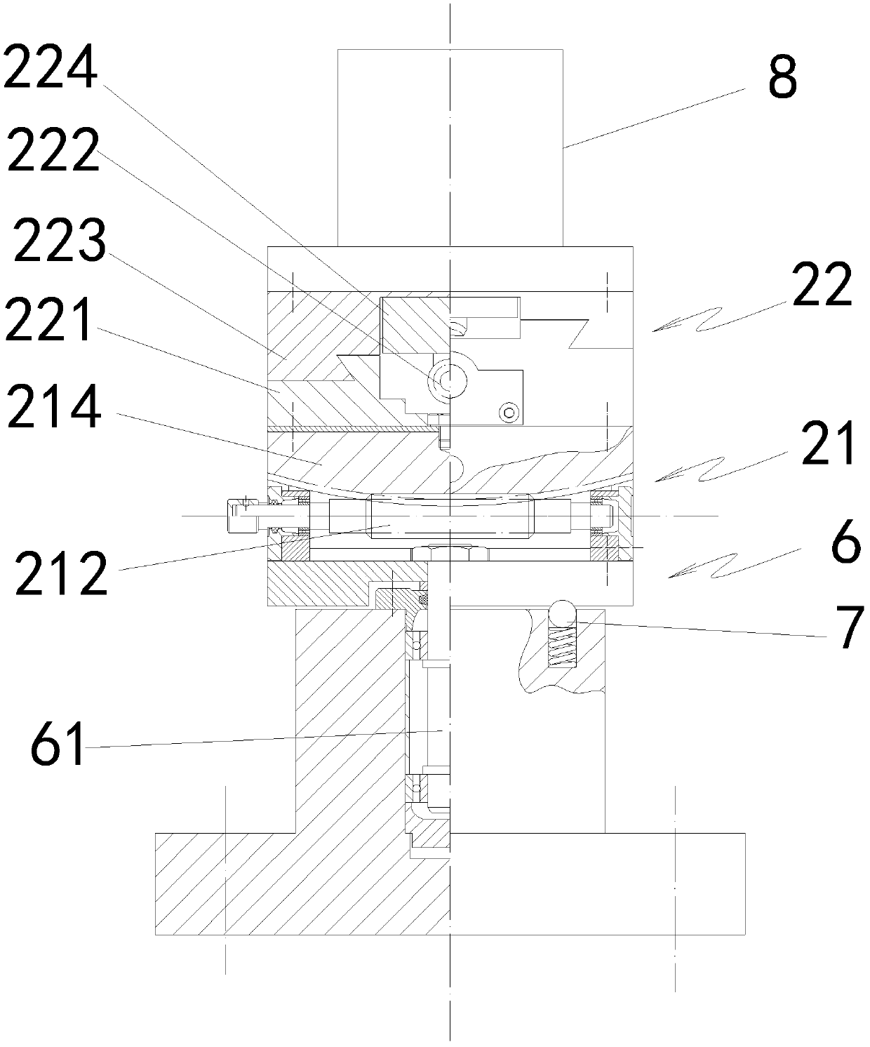
[0024] An embodiment of the measuring instrument of the present invention is Figure 2-Figure 4 As shown, it includes a base 1 and a column 5 fixed on the base 1. An optical probe 3 is installed on the column 5 to move along the vertical direction, and an electric translation platform that drives the optical probe 3 to reciprocate vertically is installed on the top of the column 5. 4. A workbench for placing and rotating parts is correspondingly provided on the base 1 under the optical probe 3 . The workbench includes a turntable 6 and an angular displacement adjustment table 2 set up from bottom to top. The turntable on the top of the turntable 6 rotates around the axis of its vertical shaft 61. The shaft 61 is supported by a precision B-grade bearing and is lifted by a spring. The positioning mechanism 7 formed by the cooperation of the steel ball and the corresponding positioning pit is indexed at 90°. In addition, the base 1 is also equipped with a grating ruler for measur...


PUM


Abstract

The invention discloses a measurement method and a measurement instrument of a revolution body part, wherein the measurement instrument comprises a base, a vertical post and an optical measurement head, wherein the vertical post is fixed on the base; the optical measurement head is movably assembled on the vertical post through a vertical orientation mode; a working platform which is used for placing and revolving a part is correspondingly arranged on the base below the optical measurement head; the working platform comprises a revolution platform and an angle displacement regulating platform which are arranged from bottom to top; the angle displacement regulating platform comprises a first angle displacement platform and a second angle displacement platform which respectively comprise a first deflection platform and a second deflection platform; and the deflection axes surrounded by the first deflection platform and the second deflection platform in rotation are vertical mutually and are both parallel to a plane of a light curtain of the optical measurement head. For the angle displacement regulating platform in the measurement instrument provided by the invention, by adopting the deflection surrounding the deflection axes parallel to the plane of the light curtain of a parallel light source through driving the two angle displacement platforms respectively by the revolution driving mechanism, the cross coupling regulation of the deflection angles of the working platform is realized, the space posture of a workpiece can be captured accurately, and the accurate positioning and measurement to the part are ensured.

Description

Technical field: [0001] The invention relates to the technical field of precision detection. Background technique: [0002] In order to realize the measurement of the outer dimensions of the parts of the revolving body, there is a method of non-contact measurement of the profile data of the parts using an optical measuring head composed of a parallel light source and a CCD image sensor in the prior art, such as a method disclosed in Chinese Patent Publication No. CN 101629816A This method relies on a rotary table to realize the rotation of the workpiece. The rotary table specifically adopts the structure of the rotation and cooperation of the shaft and the bushing to realize the rotation of the workpiece placed on the table, and cannot realize the alignment of the parts (guarantee Precise adjustment of the part axis perpendicular to the probe light curtain). At present, most of the known workbench adjustment devices realize the horizontal adjustment of the workbench through...

Claims


Application Information

Patent Timeline
Patent Type & Authority Patents(China)
IPC IPC(8): G01B11/24
Inventor 王晓强崔凤奎杨丙乾孙彩霞庞华奇张丰收徐红玉孙安李贯卿冯霞
Owner HENAN UNIV OF SCI & TECH
Learn More