Gear selecting and shifting mechanism for cam

A shifting mechanism and shifting technology, applied to controlled components, mechanical equipment, mechanical control devices, etc., can solve problems such as inconvenient control and complex structure of the shifting actuator

Inactive Publication Date: 2012-09-19
HENAN UNIV OF SCI & TECH
View PDF9 Cites 3 Cited by
  • Summary
  • Abstract
  • Description
  • Claims
  • Application Information

AI Technical Summary

Problems solved by technology

[0003] The object of the present invention is to provide a tractor electronically controlled mechanical automatic transmission gear selection mechanism with compact structure, easy installation and convenient operation, so as to solve the problems of complex structure and inconvenient control of existing gear selection actuators

Method used


Image

  • Gear selecting and shifting mechanism for cam
  • Gear selecting and shifting mechanism for cam
  • Gear selecting and shifting mechanism for cam

Examples


Embodiment Construction

[0011] The present invention will be further described in detail below in conjunction with the drawings.

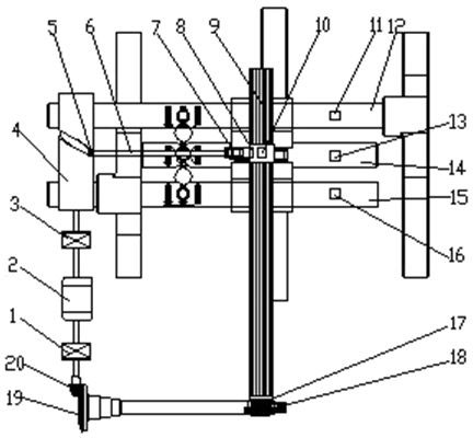
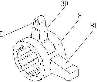
[0012] Such as figure 1 Shown is a gear selection and shift mechanism for tractors, including a gear selection mechanism and a gear shift mechanism. The gear shift mechanism includes a shift shaft 9, and the shift finger 8 is splined with the shift shaft 9 to prevent rotation. It can slide axially along the shift shaft 9. A shift fork 81 is fixed at the lower end of the shift finger 8, and three shift fork shafts 12, 14, 15 perpendicular to the shift shaft are arranged in parallel corresponding to the shift fork 81.

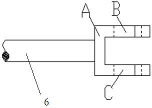
[0013] The gear selection mechanism is a cam gear selection mechanism, which includes a cylindrical rotary cam 4 arranged parallel to the shift shaft 9. The driven roller 5 of the cam is welded to one end of a driven rod 6, and the other end of the driven rod 6 is connected to the The finger sleeve 30 is hinged. When the cylindrical cam rotates, its driven roll...


PUM


Abstract

The invention relates to a gear selecting and shifting mechanism for a cam. The gear selecting and shifting mechanism comprises a gear selecting mechanism, a gear shifting mechanism and a double-shaft motor, wherein the gear selecting mechanism is a cam gear selecting mechanism and comprises a cylinder rotary cam, a rotation axis of the cylinder rotary cam and a gear shifting shaft are parellelly arranged, a driven roller is assembled in a rotary groove of the cylinder rotary cam in a guide sliding mode and linearly moves along the rotation axis when the cylinder rotary cam rotates, the driven roller is in transmission connection with a finger stall through a driven rod which is fixedly connected with the driven roller, the gear shifting finger stall is rotatingly assembled on a gear shifting finger in a limiting mode along the axial direction of the gear shifting shaft, and two output shafts of the double-shaft motor are connected with the cam and the gear shifting shaft in a driving mode through clutches which correspond to the two output shafts. The gear selecting mechanism is a transmission mechanism of the cylinder rotary cam, the gear selecting mechanism is used for driving the cylinder cam to rotate so as to drive the roller to move along a groove line of the surface of the cylinder cam, and the driven rod is enabled to drive the gear shifting finger to slide to a position of a corresponding fork shaft along the gear shifting shaft, so that gear selection is achieved.

Description

Technical field [0001] The invention relates to the field of wheel shifting mechanisms, in particular to a tractor electronically controlled mechanical shifting mechanism. Background technique [0002] In recent years, with the advancement of vehicle automatic transmission technology, the research of automatic transmission products in my country has been greatly developed, and different types of automatic transmission have appeared one after another. The shifting force required for a tractor to shift gears is relatively large, and the frequent operation of traditional manual shifting is likely to cause driver fatigue. The application of automatic transmission on tractors and the study of tractor automatic transmission technology have attracted more and more attention. In the prior art, most of the shifting mechanisms of electronically controlled mechanical automatic transmissions for vehicles adopt hydraulic control, and generally adopt the XY orthogonal arrangement of dual hydr...

Claims


Application Information

Patent Timeline
Patent Type & Authority Applications(China)
IPC IPC(8): F16H59/02F16H63/32
Inventor 徐立友赵研科周志立刘益滔丁金全李金辉郗建国牛毅曹付义
Owner HENAN UNIV OF SCI & TECH
Why Eureka
Try Eureka