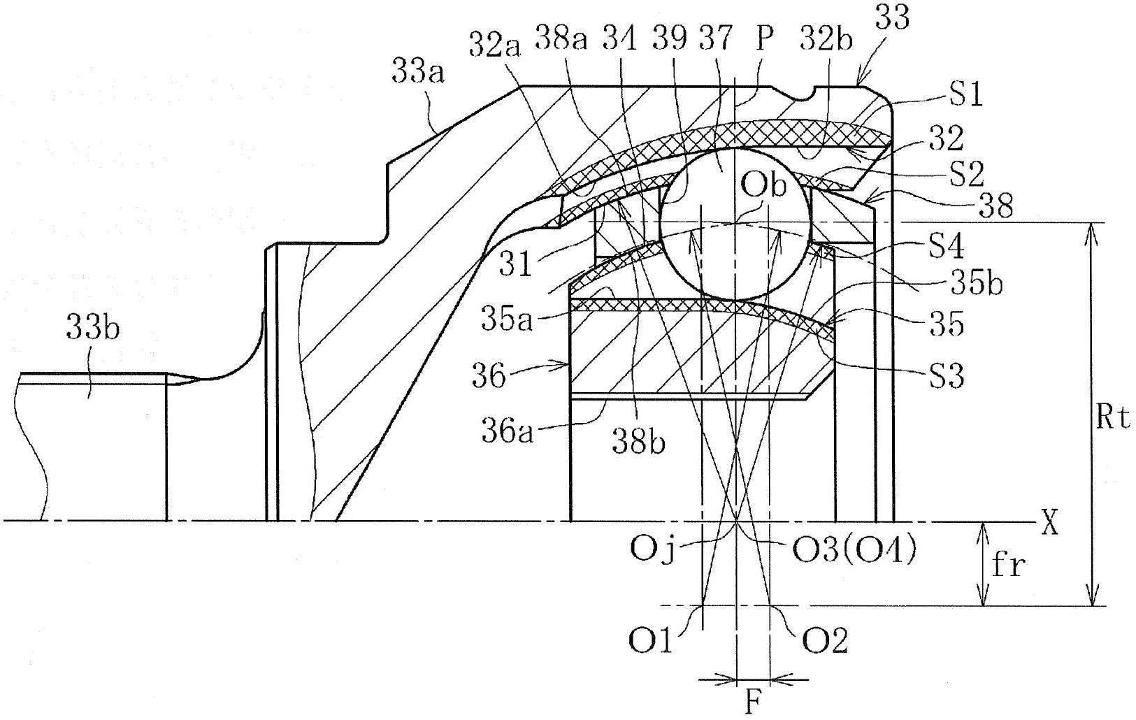
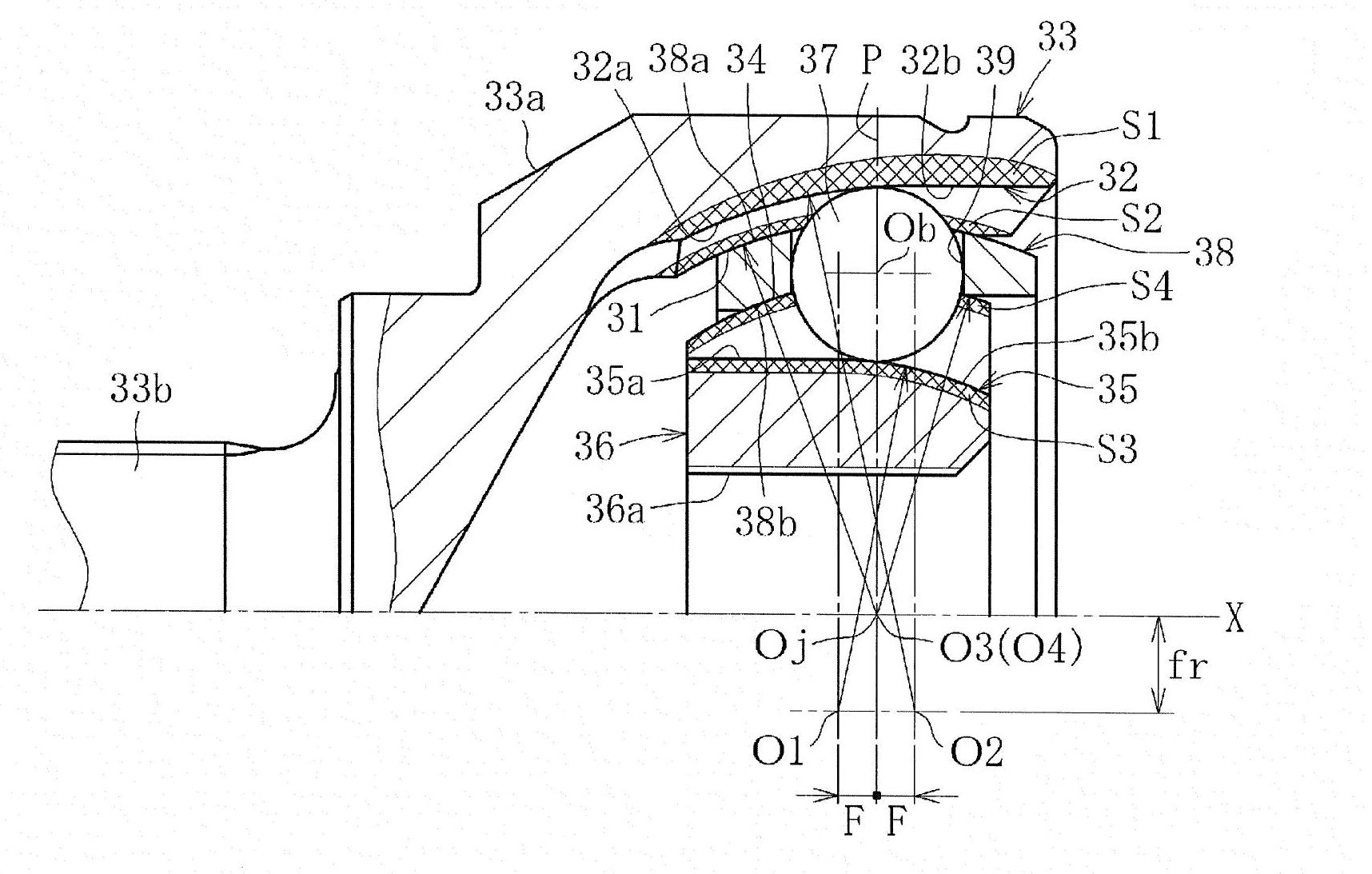
Stationary constant-velocity universal joint
A constant velocity universal joint and outer joint technology, applied in the direction of gear transmission mechanism, elastic coupling, mechanical equipment, etc., can solve the problem of no track groove, etc., to improve the torsional strength, improve the torsional fatigue strength and quasi-static The effect of improving torsional strength and torque transmission efficiency
- Summary
- Abstract
- Description
- Claims
- Application Information
AI Technical Summary
Problems solved by technology
Method used
Image


Examples
Embodiment 1
[0120] Example 1 (in Example 1 and Example 2 described later, the outer joint member is called an outer ring, and the inner joint member is called an inner ring)
[0121] A durability test at a common angle (operating angle of 6°) under high torque conditions was carried out, and the results are shown in Table 2 below. In this case, two samples of conventional products (conventional product No. 1, conventional product No. 2) were produced, and two samples of the above-mentioned invention product A1 (invention product A1 No. 1, invention product A1 No. 2) were produced. , respectively manufacture four samples of the invention product A2 and invention product B (invention product A2No.1, invention product A2No.2, invention product A2No.3, invention product A2No.4, invention product B1No.1, invention product B1No .2, Invention B1No.3, Invention B1No.4). The durability test was carried out under the conditions of a torque of 834 Nm and a rotational speed of 230 r / min.
[0122] [...
Embodiment 2
[0127] Next, an endurance test at a high angle was carried out, the results of which are shown in Table 3 below. In this case, two samples of conventional products (conventional product No. 1, conventional product No. 2), and two samples of invention product A1, invention product A2, and two invention products of product B (invention product A1, No. 1, Invention A1No.2, Invention A2No.1, Invention A2No.2, Invention B1No.1, Invention B1No.2). The durability test was carried out under the conditions of a torque of 549 Nm, an angle of 0 to 46° (swing), and a rotation speed of 80 r / min.
[0128] [table 3]
[0129]
[0130] In the case of running for 3.7 hours, conventional product No. 1 and conventional product No. 2 had defects caused by lack of tracks in the track grooves on the inner side of the outer ring. Therefore, the two conventional products continued to operate only by replacing the outer ring with a new one, but in the case of running for 7.4 hours, the conventiona...
Embodiment 3
[0136] Next, a rotational torsional strength test was performed. In this test, the operating angle was set at 46°, and the torque was gradually increased in a state of low-speed constant rotation until it was broken, and the strength was evaluated based on the torque value at the time of breakage. The result is in Figure 16 The graph and shown in Table 5 below. In conventional products, the inner ring is replaced with the invention specification (a) of Table 4, the cage is replaced with the invention specification (b) of Table 4, and the outer ring is replaced with the invention specification of Table 4 ( c), components of the invention specification (d) in which the outer ring is replaced by Table 4, components of the invention specification in which the inner ring, cage, and outer ring are replaced by (a), (b) and (c), respectively, Invention product B1 was tested with members of the invention specifications substituted for (a), (b), (c), and (d).
[0137] [table 5]
[...
PUM
 Abstract
Description
Claims
Application Information
 - R&D
- Intellectual Property
- Life Sciences
- Materials
- Tech Scout
- Unparalleled Data Quality
- Higher Quality Content
- 60% Fewer Hallucinations
Browse by: Latest US Patents, China's latest patents, Technical Efficacy Thesaurus, Application Domain, Technology Topic, Popular Technical Reports.
© 2025 PatSnap. All rights reserved.Legal|Privacy policy|Modern Slavery Act Transparency Statement|Sitemap|About US| Contact US: help@patsnap.com