
Device having a plug-in connection

A technology of plug connection and driving side, which is applied in the direction of rigid shaft coupling, elastic coupling, friction clutch, etc., and can solve the problems of tooth tolerance and high manufacturing cost

Active Publication Date: 2014-11-26
SCHAEFFLER TECH AG & CO KG
View PDF6 Cites 0 Cited by
  • Summary
  • Abstract
  • Description
  • Claims
  • Application Information

AI Technical Summary

Problems solved by technology

[0003] Because of the tolerance of the predetermined peripheral play of the teeth, the plug connection tilts and generates noise
The reduction of the tolerances of the teeth increases the manufacturing costs and is only partially successful

Method used


Image

  • Device having a plug-in connection
  • Device having a plug-in connection
  • Device having a plug-in connection

Examples


Embodiment Construction

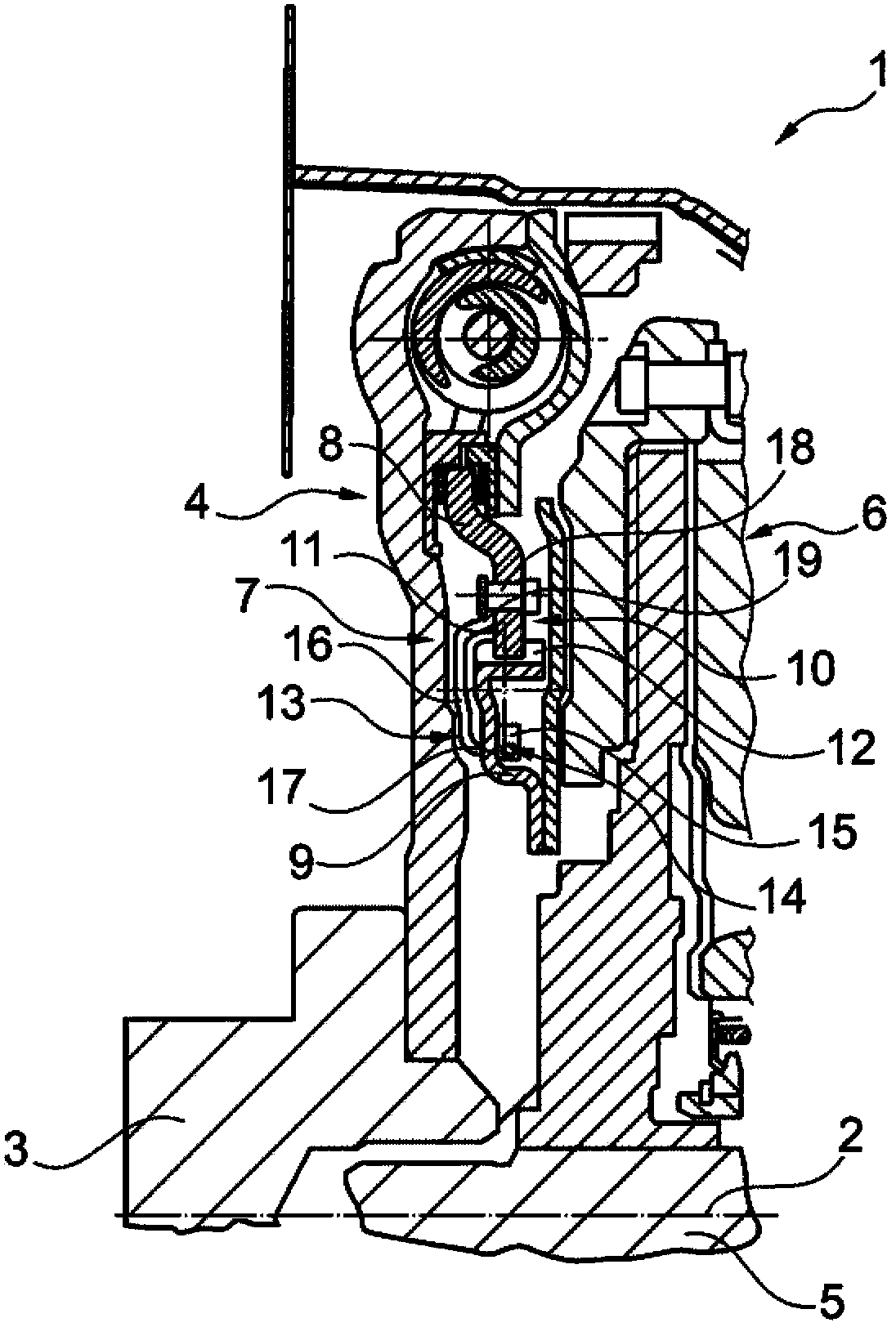
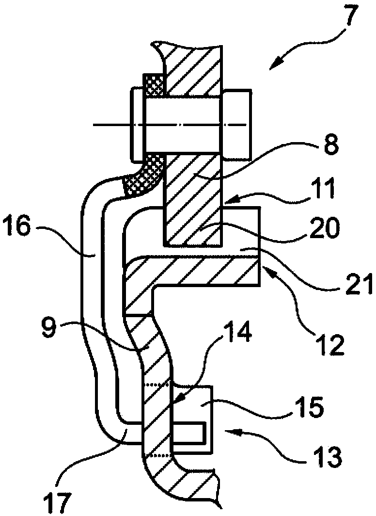
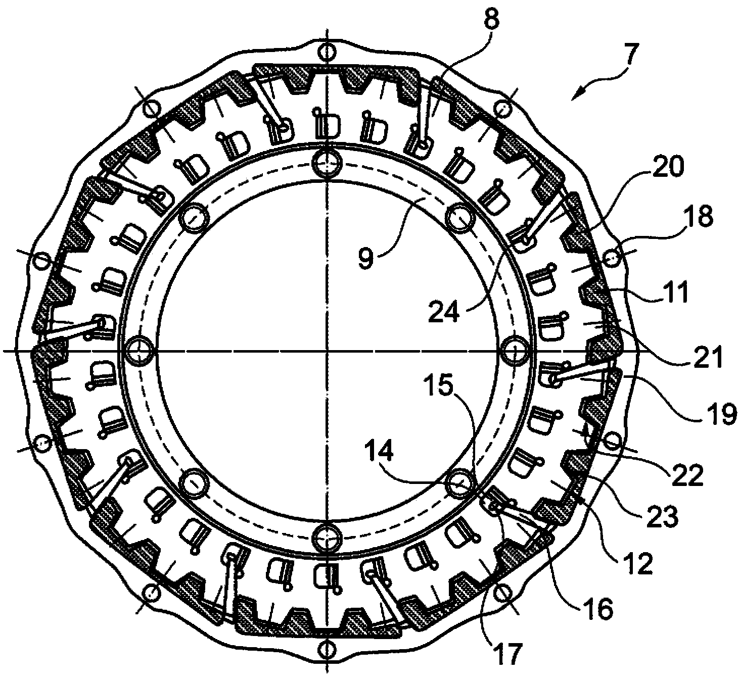
[0018] figure 1 Shown in partial section is a device 1 mounted around an axis of rotation 2 with a rotational vibration damper 4 fixedly received on the crankshaft 3 of an internal combustion engine on the drive side, such as a dual-mass flywheel, and received on the driven side by a transmission The friction clutch 6 on the input shaft 5 , shown only partially, can also be a double clutch. Before the final installation of the device 1, the rotational vibration damper 4 received on the crankshaft 3 of the drive train attached to the structural group fixed on the engine side and the friction clutch 6 received on the transmission input shaft 5 are used in the final installation by means of plug-in The plug connections 7 are connected to one another in a rotationally fixed manner. The plug connection 7 is formed with a drive-side part 8 , here the output side of the torsional vibration damper 4 , and a driven-side part 9 , here a plate connected to the input side of the frictio...


PUM


Abstract

The invention relates to a plug-in connection between an input-side component and an output-side component of a drive train of a motor vehicle, wherein outer toothing and inner toothing complementary thereto are provided in order to form the plug-in connection by means of a toothing. In order to cost-effectively brace the toothing in the circumferential direction, a plurality of fingers is provided radially outside of the toothing on a component. Said fingers are distributed over the circumference and are directed radially inward and overlap the toothing radially. Said fingers protrude axially into openings, which are provided on the other component and which are at least partially covered by means of tongues, in order to form an elastic bracing mechanism.

Description

technical field [0001] The invention relates to a device with a plug connection between a drive-side part and a driven-side part of a drive train of a motor vehicle, wherein external teeth and complementary internal teeth are provided to utilize the teeth on said parts Form a plug connection. Background technique [0002] For example, DE 10 2008 027 443 A1 discloses a device in the form of a plug-in clutch assembly in a motor vehicle drive train. Here, the clutch assembly consists of two subunits, which are connected in a rotationally locked manner by means of a plug connection, so that one subunit is fastened to the crankshaft of the internal combustion engine and the other receives the On the transmission input shaft of a transmission, for example a dual clutch transmission, or can be fastened to the transmission in another way. During final assembly, the engine assembly with the internal combustion engine and the transmission assembly with the transmission are connected...

Claims


Application Information

Patent Timeline
Patent Type & Authority Patents(China)
IPC IPC(8): F16D3/14F16D13/70
CPCF16D2001/103F16D2013/703F16D13/70F16D3/14
Inventor R·埃德尔
Owner SCHAEFFLER TECH AG & CO KG
Learn More