
Lead spot welding tooling and line spot welding method for sound films of loudspeakers

A speaker and sound film technology, applied in the field of speaker sound film point and line tooling, can solve problems such as the inability of the speaker to produce sound, the quality of the speaker and the pure sound of the speaker, etc., to avoid fatigue disconnection, improve sound quality, and reduce the overall load. Effect

Active Publication Date: 2012-09-12
BESTAR HLDG
View PDF3 Cites 7 Cited by
  • Summary
  • Abstract
  • Description
  • Claims
  • Application Information

AI Technical Summary

Problems solved by technology

[0002] At present, the dot line method of the sound film is to lead the two lead wires of the voice coil from the same point, and fix the two lead wires on the sound film with glue, and then point the lead wire of the voice coil on the sound film with glue. The disadvantage of this dot line method Yes: Since the two voice coil lead wires are led out from the same point, and the two lead wires are in contact with each other, after the long-term vibration and friction of the sound film, the insulating layer on the two lead wires is often scratched, causing the two lead wire conductors to contact to form a short circuit, so that the speaker will At the same time, use glue to point the voice coil lead on the sound film. When vibrating, the voice coil lead will vibrate with the sound film, which will easily cause fatigue and disconnection of the lead; and glue the voice coil On the sound film, the load on the sound film is increased, resulting in a decrease in the pure tone of the speaker and an increase in distortion; at the same time, this method of dotted lines requires a lot of manual collaboration to complete, and the shape and amount of glue of the dotted lines are completely controlled manually. It is easy to cause the quality of the speaker to deteriorate

Method used


Image

  • Lead spot welding tooling and line spot welding method for sound films of loudspeakers
  • Lead spot welding tooling and line spot welding method for sound films of loudspeakers
  • Lead spot welding tooling and line spot welding method for sound films of loudspeakers

Examples


Embodiment Construction

[0025] The present invention will be further described below in conjunction with the accompanying drawings and specific embodiments.

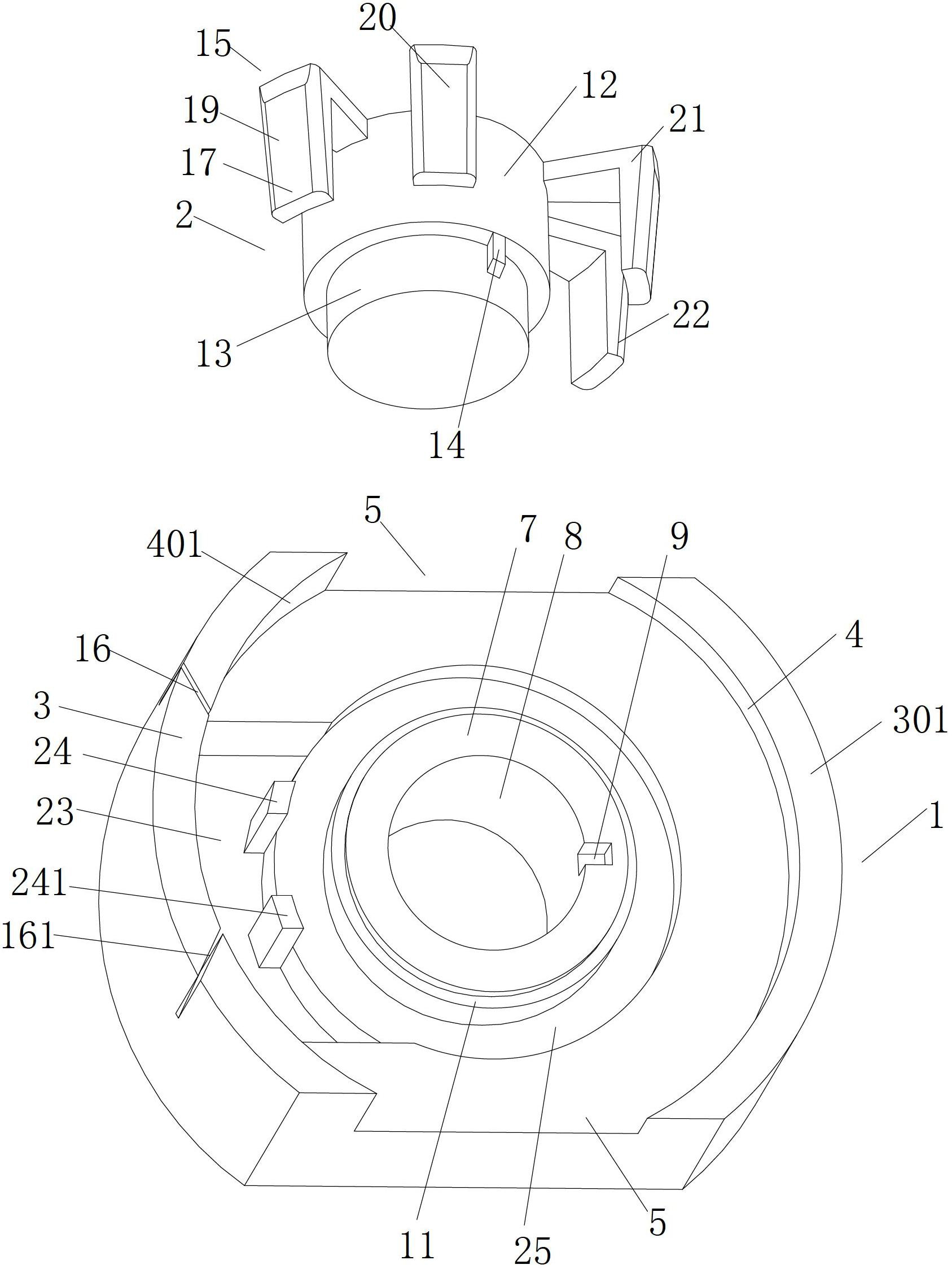
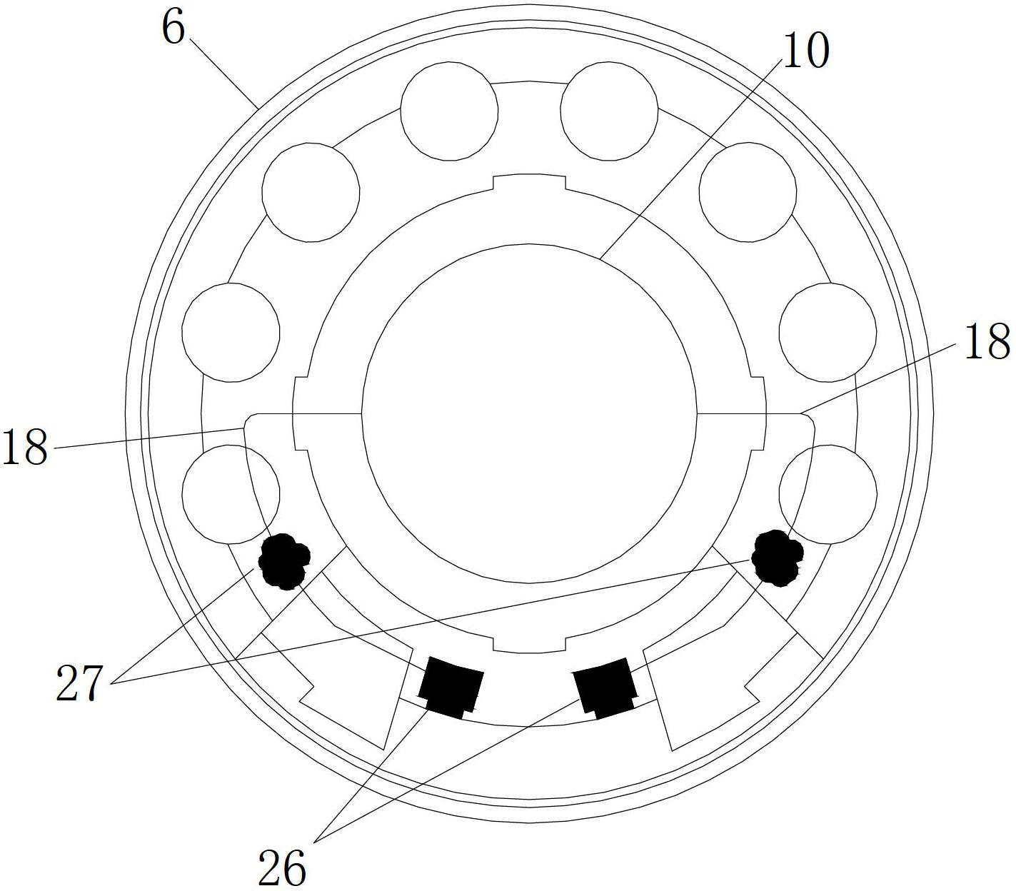
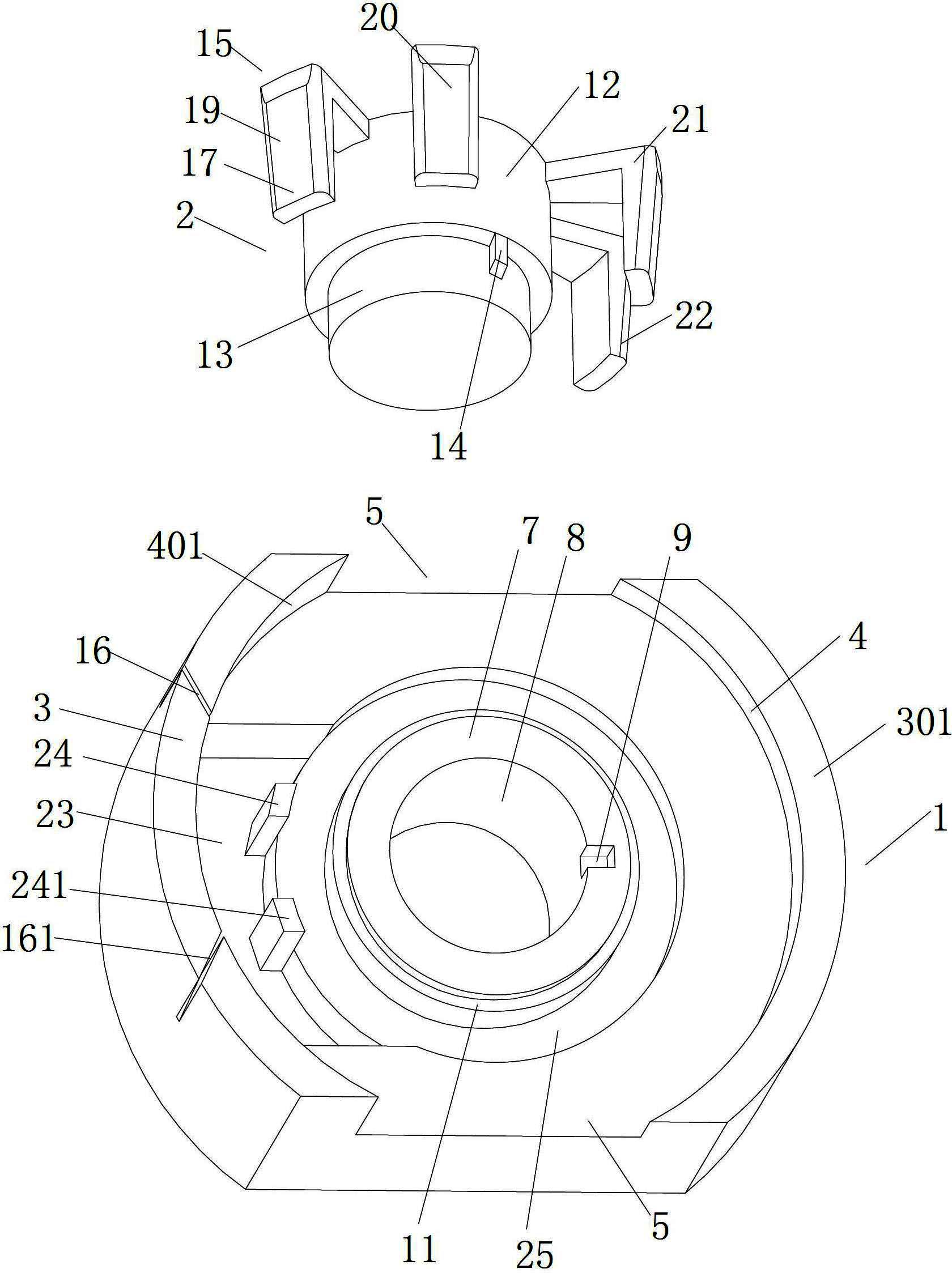
[0026] see figure 1 , 2 , loudspeaker sound film dot line tooling, which includes a lower base 1, an upper pressure seat 2 arranged on the lower base 1 and matched with the lower base; the upper end surface of the lower base 1 is provided with two upwardly protruding arc limit ribs 3 , 301, there are two arc-shaped limit ribs, the limit surfaces 4 and 401 of the two arc-shaped limit ribs are on the same circle, and there is a gap between the two arc-shaped limit ribs 5. It is easy to take and place the pot frame 6, and when the circular pot frame 6 is placed on the lower base 1, it is limited by two arc-shaped limit ribs 3, 301, so that the pot frame cannot be left and right , move back and forth; clamping notches 16, 161 are set on one of the arc-shaped limit ribs 3; in the middle of the upper end surface of the lower base 1, an upwardly rai...


PUM


Abstract

The invention relates to a lead spot welding tooling and a lead spot welding method for sound films of loudspeakers. The lead spot welding tooling comprises a lower base and an upper press base. The upper end face of the lower base is provided with limit flanges and a boss. The boss is provided with a positioning hole. The inner wall of the positioning hole is provided with a positioning groove. An annular step surface for mounting a sound coil is arranged at the upper end of the boss. The upper press base comprises a first base body and a second base body inserted into the positioning hole. The diameter of the first base body is larger than the diameter of the positioning hole. The second base body is provided with a positioning insert matched with the positioning groove. Lead retaining support legs are arranged on two side walls of the first base body. The limit flanges are respectively provided with a lead clamping notch. Two leads of the sound coil are subjected to spot welding on a frame without mutual contact, are loosened sufficiently and cannot vibrate along with the sound films, so that breakage of the leads due to fatigue is effectively avoided, and the service life of products is prolonged. Further, the integral load of the sound films is reduced, the loudspeakers are better in pure tone and low in distortion, operation can be completed by only one person, work efficiency is improved and labor cost is reduced.

Description

technical field [0001] The invention belongs to the technical field of electronic devices, in particular to a loudspeaker in the field of electronic devices, and more specifically to a loudspeaker sound film dot line tooling and a method thereof. Background technique [0002] At present, the dot line method of the sound film is to lead the two lead wires of the voice coil from the same point, and fix the two lead wires on the sound film with glue, and then point the lead wire of the voice coil on the sound film with glue. The disadvantage of this dot line method Yes: Since the two voice coil lead wires are led out from the same point, and the two lead wires are in contact with each other, after the long-term vibration and friction of the sound film, the insulating layer on the two lead wires is often scratched, causing the two lead wire conductors to contact to form a short circuit, so that the speaker will At the same time, use glue to point the voice coil lead on the sound...

Claims


Application Information

Patent Timeline
IPC IPC(8): H04R9/04H04R31/00
Inventor 莫丽丽徐文斌张秀琴李红元吴逸飞
Owner BESTAR HLDG
Learn More