
Projection device and lens module

A technology of lens module and projection device, which is applied in the direction of projection device, installation, optics, etc., can solve the problems of unfavorable miniaturization design of projection device, and achieve the effect of smooth focusing, small volume and reduced alignment

Active Publication Date: 2014-10-29
YOUNG OPTICS
View PDF11 Cites 0 Cited by
  • Summary
  • Abstract
  • Description
  • Claims
  • Application Information

AI Technical Summary

Problems solved by technology

However, the above-mentioned patents all adopt complex mechanism designs, which tend to produce unpredictable manufacturing tolerances during manufacture, and are not conducive to the miniaturization design of the projection device.

Method used


Image

  • Projection device and lens module
  • Projection device and lens module
  • Projection device and lens module

Examples


Embodiment Construction

[0034] The foregoing and other technical contents, features, and effects of the present invention will be clearly presented in the detailed description of multiple embodiments below with reference to the drawings. The directional terms mentioned in the following embodiments, such as "up", "down", "front", "rear", "left", "right", etc., are only directions for referring to the attached drawings. Therefore, the directional terms used are used to illustrate rather than to limit the present invention.

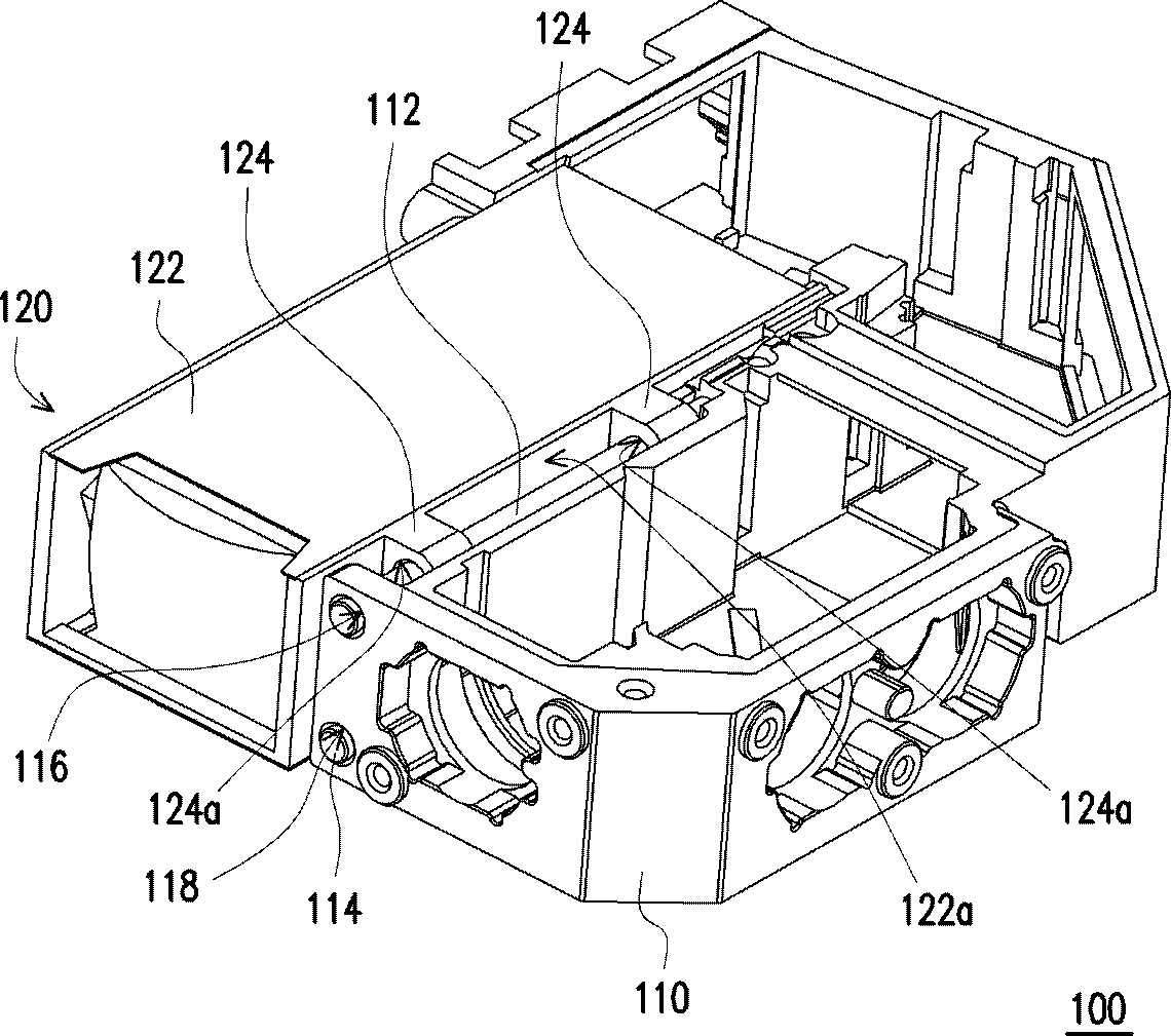
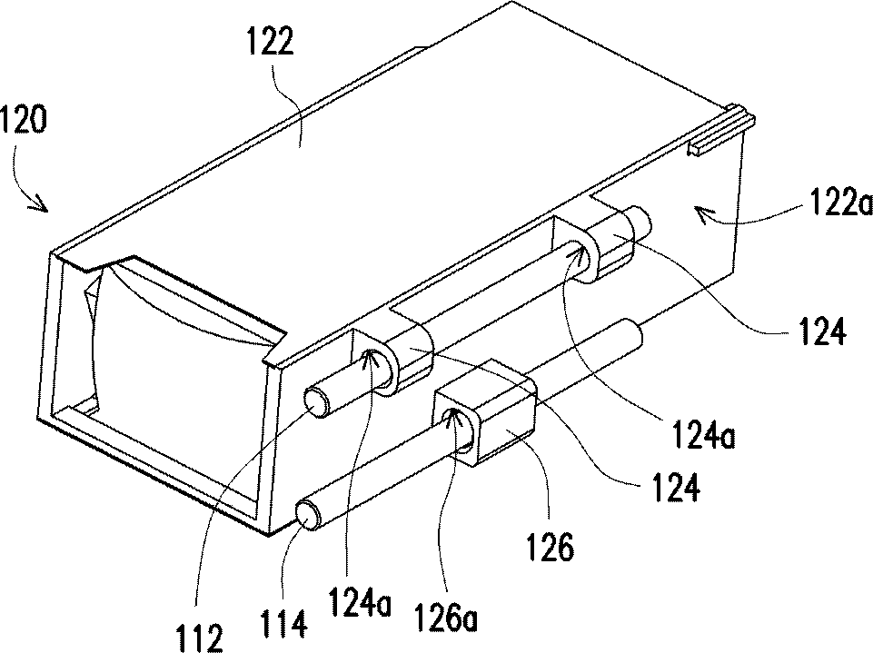
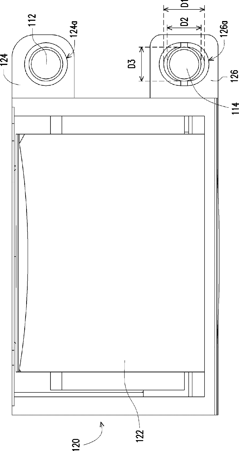
[0035] figure 1 It is a perspective view of a projection device according to an embodiment of the invention. figure 2 for figure 1 A three-dimensional view of the lens module, the first guide rod and the second guide rod. Please refer to figure 1 and figure 2 The projection device 100 of this embodiment includes an optical engine base 110 and a lens module 120. The optical engine base 110 has a first guide rod 112 and a second guide rod 114, and the first guide rod 112 is substanti...


PUM


Abstract

The invention provides a projection device and a camera lens module. The projection device comprises an optical mechanical seat and a camera lens module. The optical mechanical seat is provided with a first guide rod and a second guide rod. The first guide rod is substantially parallel to the second guide rod. The camera lens module comprises a main body, at least a first bump and a second bump. The main body is provided with a side surface. The first bump is formed at the side surface and provided with a first through hole. The first bump is slidably disposed at the first guide rod via the first through hole. The second bump is formed at the side surface and provided with a second through hole. The second bump is slidably disposed at the second guide rod via the second through hole. The camera lens module is used for movement relative to the optical mechanical seat along the first guide rod and the second guide rod.

Description

【Technical Field】 [0001] The invention relates to an optical device and its lens module, and more particularly to a projection device and its lens module. 【Background technique】 [0002] The projection device is a display device that can generate images anytime and anywhere. The imaging principle of the projection device is to convert the illumination beam generated by the light source into an image beam through a light valve, and then project the image beam onto the screen or wall through the lens to form an image. With the advancement of projection technology and the reduction of manufacturing costs, the use of projection devices has gradually expanded from commercial use to household use. Recently, all kinds of electronic products are developing towards high-speed, high-efficiency, light, thin, short and small trends, which can have the advantages of being portable and free of space restrictions. [0003] Generally speaking, the lens module of the projection device can be slid...

Claims


Application Information

Patent Timeline
Patent Type & Authority Patents(China)
IPC IPC(8): G03B21/14G03B21/00G02B7/04
Inventor 黄绍华林维赐
Owner YOUNG OPTICS
Learn More