Mechanical power output device

An output device, mechanical power technology, applied in mechanical equipment, machines/engines, engines, etc., can solve the problems of narrow driving force action range, limited driving force force range, unable to achieve the purpose of action, etc., to achieve the driving form Variety, wide power range, simple structure effect

Inactive Publication Date: 2014-11-19
胡润富
View PDF6 Cites 0 Cited by
  • Summary
  • Abstract
  • Description
  • Claims
  • Application Information

AI Technical Summary

Problems solved by technology

[0005] At present, the existing mechanical power output device can only move up and down and provide vertical power. In this way, the force range of the driving object is very narrow, and the force range of the driving object is not only very limited, but also too single to achieve the ideal action purpose.

Method used


Image

  • Mechanical power output device
  • Mechanical power output device
  • Mechanical power output device

Examples


Embodiment 1

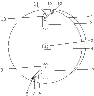
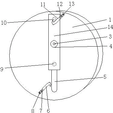
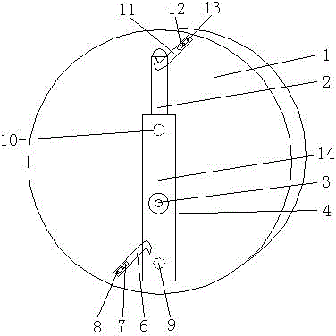
[0032] Such as Figure 1-Figure 11 As shown, a mechanical power output device includes a mounting base 20 on which a turntable 1 is connected via a first bearing 19 . The turntable 1 is vertically provided with a U-shaped hole, and the U-shaped hole is divided into a first U-shaped hole 2 and a second U-shaped hole 5 . The turntable 1 is movably installed with a moving plate 14 through the first U-shaped hole 2 and the second U-shaped hole 5. The specific installation method is: the upper and lower ends of the moving plate 14 are respectively provided with the first U-shaped hole 2. Match the first connecting rod 9 and the second connecting rod 10 with the second U-shaped hole 5, and the connecting rods respectively pass through the U-shaped hole and stretch out to the other side of the turntable. On this side, the protruding end of the first connecting rod 9 A first balancer 15 is installed through the first mounting part 16 , and a second balancer 17 is mounted through the ...


PUM


Abstract

Disclosed is a mechanical power outputting device, comprising a fitting seat (20), characterized in that a turntable (1) is hinged on the fitting seat (20), two U-shaped holes (2, 5) are provided on the turntable (1), a movable plate (14) is movably mounted in the U-shaped holes (2, 5), hooks (6, 11) are respectively provided on parts of the turntable (1) above or below the movable plate (14), a retractable arm (31) and balancers (15, 17) are mounted on the movable plate (14), a track guiding element (28) guiding the offset direction of the movable plate (14) is provided above the U-shaped holes (2, 5), the track guiding element (28) being mounted on the fitting seat (20), a snapping position (27) for controlling the rotation of the turntable (1) is further provided on the periphery of the turntable (1), and a snap (25) corresponding to the snapping position (27) is provided on the fitting seat (20). The retractable arm (31), the snap (25) and the track guiding element (28) are connected to a control box (26) to control the actions thereof. A protruding output shaft (24) is further provided on the turntable (1), and rollers (21, 22, 23) are respectively provided on the inner sides of upper and lower ends of the movable plate (14) and the balancers (15, 17). The mechanical power outputting device has a wide power range and a simple structure, can be driven in various manners and is convenient to use.

Description

[0001] claim national priority [0002] This application is based on the Chinese patent application No. 201120523426.7 submitted on December 15, 2011. The title of the invention is a mechanical power device claiming domestic priority, and the entire content of the application is hereby cited as a reference. technical field [0003] The present invention relates to a mechanical power device, more specifically to a mechanical power device with a power range of 360 degrees. Background technique [0004] The mechanical power output device is a device that provides an initial force through the driving object and then makes the driving object act under the force of the device. [0005] At present, the existing mechanical power output device can only move up and down and provide vertical power. In this way, the force range of the driving object is very narrow, and the force range of the driving object is not only very limited, but also too single to achieve the ideal action purpose...

Claims


Application Information

Patent Timeline
Patent Type & Authority Patents(China)
IPC IPC(8): F03G3/00
CPCF03G3/00
Inventor 胡润富
Owner 胡润富
Why Eureka
Try Eureka