
Vibration isolation system of vibrating centrifuge

A technology for vibrating centrifuges and vibration isolation systems, applied in centrifuges and other directions, can solve problems such as the resonance of the rotating arm system, the reduction of the reliability of the centrifuge system, and the design of the natural frequency of the leaf spring, and achieve high static stiffness, light weight, dynamic Effects of small stiffness and natural frequencies

Inactive Publication Date: 2012-09-05
GENERAL ENG RES INST CHINA ACAD OF ENG PHYSICS
View PDF3 Cites 3 Cited by
  • Summary
  • Abstract
  • Description
  • Claims
  • Application Information

AI Technical Summary

Problems solved by technology

Because the design of the natural frequency of the leaf spring is difficult, if the design is not proper, it is easy to cause the resonance of the arm system
In addition, for large-capacity vibrating centrifuges, the mass of the rotating arm system is relatively large. If this hoisting method is still used, the reliability of the entire centrifuge system will be reduced.

Method used


Image

  • Vibration isolation system of vibrating centrifuge
  • Vibration isolation system of vibrating centrifuge
  • Vibration isolation system of vibrating centrifuge

Examples


Embodiment Construction

[0030] Below in conjunction with accompanying drawing, the present invention is described in further detail:

[0031] Such as figure 1 As shown, the present invention includes two sets of vibration isolation devices 3 with the same structure, and the two sets of vibration isolation devices 3 are symmetrically installed on the swing arm system support 2 on both sides of the swing arm support 1 of the vibrating centrifuge, and the swing arm system support 2 is on the When working, it will slide in both directions relative to the arm support 1 (such as figure 1 indicated by the middle arrow).

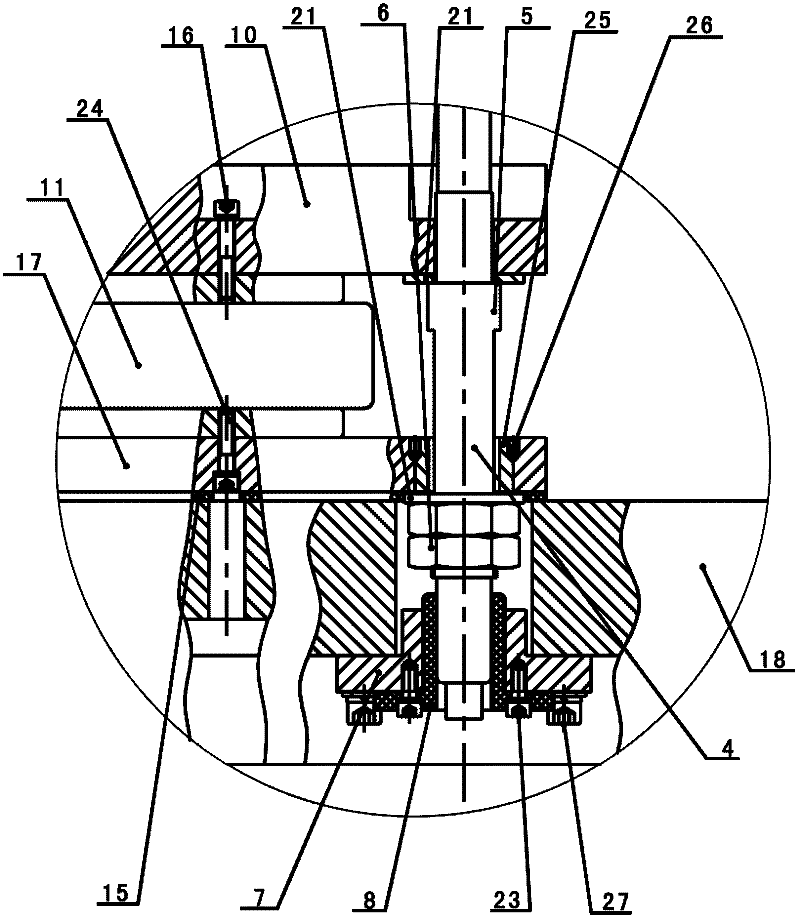
[0032] Such as Figure 1-Figure 7As shown, each set of vibration isolation device 3 includes a force sensor 14, an upper rigid plate 10, a middle rigid plate 17, a lower rigid plate 18, a guide rod 4, a linear bearing 8, an adjustment block 7 and an air spring 11, to The axial direction of the guide rod 4 is the up-down direction, the upper end of the guide rod 4 is connected with the r...


PUM


Abstract

The invention discloses a vibration isolation system of a vibrating centrifuge. The vibration isolation system comprises a vibration isolation device, wherein the vibration isolation device comprises a guide rod, the axial direction of the guide rod is taken as the up-and-down direction, the upper end of the guide rod is connected with a rotating arm support of the vibrating centrifuge, the lower end of the guide rod sequentially penetrates through an upper-layer rigid plate, a middle-layer rigid plate and a lower-layer rigid plate, a linear bearing is connected with a regulating block, the regulating block is mounted on the lower-layer rigid plate, the lower end of the guide rod penetrates through the linear bearing, the two ends of the lower-layer rigid plate are respectively connected with the inner side of a support of a rotating arm system of the vibrating centrifuge, a force sensor is positioned between the rotating arm support and the upper-layer rigid plate, and an air spring is positioned between the upper-layer rigid plate and the middle-layer rigid plate. By adopting the structure that the air spring cooperates with the rigid plates, the imbalance force of the support of the rotating arm system relative to the rotating arm support is buffered and the vibration isolation purpose can be achieved. The vibration isolation system disclosed by the invention has the advantages of small dynamic rigidity, small inherent frequency, great static rigidity, good vibration isolation performance and capabilities of isolating vibration waves with higher frequency and bearing greater imbalance force.

Description

technical field [0001] The invention relates to a vibration isolation system for a vibrating centrifuge, in particular to a vibration isolation system used for vibration isolation between a rotating arm system support and a rotating arm support of a vibrating centrifuge, with small dynamic stiffness and natural frequency and high static stiffness. Background technique [0002] Vibrating centrifugal compound centrifuge is referred to as vibrating centrifuge, including geotechnical vibrating centrifuge and routine vibrating centrifuge. [0003] The geotechnical vibrating centrifuge is mainly used for the research of geotechnical engineering earthquake problems. It can provide a test model vibration centrifugal composite environment to simulate the stress conditions in the prototype stress field and accurately reproduce the real dynamic response of the prototype under actual stress conditions. At present, the geotechnical vibrating centrifuge has developed from one-dimensional ...

Claims


Application Information

Patent Timeline
IPC IPC(8): B04B15/00
Inventor 冉光斌胡绍全刘小刚宋琼黎启胜陈文颖洪建忠吴文凯林明
Owner GENERAL ENG RES INST CHINA ACAD OF ENG PHYSICS
Learn More