
Self-optimization multi-level voltage reactive power control method

A technology of voltage and reactive power control and control methods, applied in the direction of reactive power compensation, reactive power adjustment/elimination/compensation, etc., can solve the problem of surplus reactive power in the entire network, compensation devices at all levels do not support each other, and cannot make full use of the entire network. Reactive power resources and other issues in the network can be improved to improve the voltage pass rate, reduce line loss, and improve the voltage pass rate of the entire network

Active Publication Date: 2012-08-29
江苏今越控股集团有限公司
View PDF5 Cites 5 Cited by
  • Summary
  • Abstract
  • Description
  • Claims
  • Application Information

AI Technical Summary

Problems solved by technology

[0009] At present, the problem of reactive power compensation in rural power grids is that the reactive power compensation devices at all levels take the local reactive power compensation resources and local voltage as the control target, and there is no mutual support between the compensation devices at all levels, and the reactive power resources of the entire network cannot be fully utilized.
In the situation where there is surplus reactive power in the entire network and the local voltage is low, the resources of the entire network are not fully utilized

Method used


Image

  • Self-optimization multi-level voltage reactive power control method
  • Self-optimization multi-level voltage reactive power control method
  • Self-optimization multi-level voltage reactive power control method

Examples


Embodiment Construction

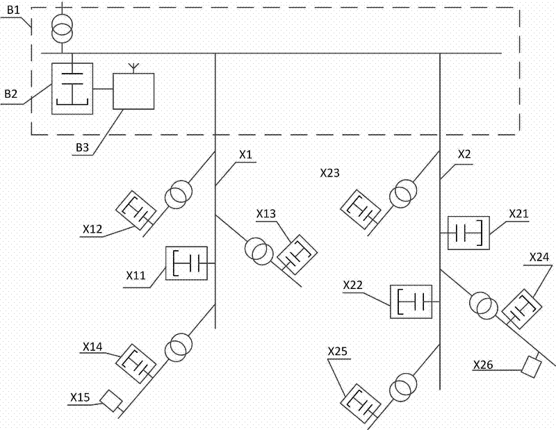
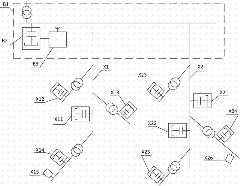
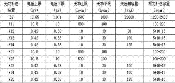
[0038] A self-optimizing multi-level voltage and reactive power control method, taking a typical substation and the following distribution network as an example. Configure a multi-level compensation controller to adjust the voltage lower limit of reactive power compensation devices at all levels. The reactive power compensation devices at all levels can make optimal adjustments to local reactive power according to the new voltage adjustment range at any time, so that the reactive power of the entire network It can be fully utilized to reduce the low voltage rate of the whole network.

[0039] Whole network configuration: 66kV / 10kV substation has two 10kV distribution lines. The substation reactive power compensation device B2 and the multi-level compensation controller B3 are installed in the substation B1.

[0040]The first 10KV power distribution line X1 is equipped with line compensation device X11, station area reactive power compensation device X12, station area reacti...


PUM


Abstract

The invention discloses a self-optimization multi-level voltage reactive power control method which aims at improving the percent of pass of network voltage. A multi-level compensating controller is in communication connection with a transformer substation, a line, a distribution room three-level reactive compensation device and a voltage monitoring terminal which can be automatically controlled according to a nine-zone diagram manner, a nine-zone diagram lower limit voltage value of the reactive compensation device can be adjusted in an increment manner by using a dynamic self-optimization multi-level control method, and the utilization rate of a compensation capacitor can be further improved, as each level reactive compensation device is supported and compensated nearby, so that the condition that the low voltage of a whole network can be minimum is realized. As the reactive power control can be carried out on the voltage of the whole network by using the method, the cost is low, the effect is direct, the implement is easy, and the problems that remained resources of the whole network reactive compensation device can not be utilized automatically, the line loss can not be reduced, and the percent of pass of the voltage is low can be solved.

Description

technical field [0001] The invention belongs to the field of power grid reactive power compensation, and relates to a reactive power compensation method for a rural power grid, in particular to a self-optimizing multi-level voltage reactive power control method. technical background [0002] At present, the main structure of my country's rural power grid is as follows: 110kV / 10kV or 66kV / 10kV substation is used as the power supply, and the power is sent to the 10kV / 0.4kV substation area through the 10kV high-voltage line, and the power is sent to the terminal by the distribution transformer and the low-voltage line. user. The rural power grid has the following characteristics: [0003] 1. The load is scattered, the line is long, and the voltage of the end user is low; [0004] 2. The seasonality of the load is strong, and the load during the busy farming period is more than ten times larger than that during the slack season; [0005] In recent years, with the continuous de...

Claims


Application Information

Patent Timeline
IPC IPC(8): H02J3/18
CPCY02E40/30
Inventor 张浩
Owner 江苏今越控股集团有限公司
Learn More