
Metal damper provided with restraining devices and stiffening ribs

A metal damper and restraint device technology, which is applied to building components, earthquake-proof and other directions, can solve problems such as the initial stiffness of buckling, and achieve the effects of preventing out-of-plane buckling, facilitating welding, and ensuring energy dissipation capacity and stability.

Inactive Publication Date: 2012-08-22
SHANGHAI SAFE SEISMIC RETROFIT & VIBRATION CONTROL TECH
View PDF9 Cites 4 Cited by
  • Summary
  • Abstract
  • Description
  • Claims
  • Application Information

AI Technical Summary

Problems solved by technology

[0005] The purpose of the present invention is to overcome the existing technical deficiencies, and propose a metal damper provided with a restraint device and a stiffener, which overcomes the existing steel plate that is prone to buckling when shearing in the plane and the initial stiffness of the steel plate that is stressed outside the plane. low defect

Method used


Image

  • Metal damper provided with restraining devices and stiffening ribs
  • Metal damper provided with restraining devices and stiffening ribs
  • Metal damper provided with restraining devices and stiffening ribs

Examples


Embodiment 1

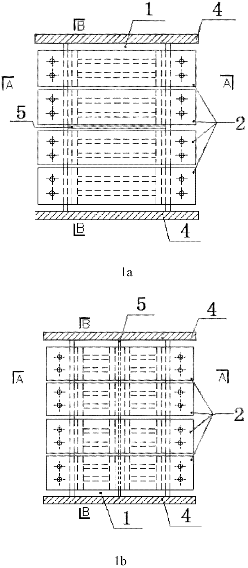
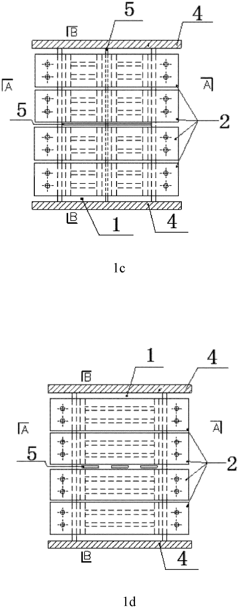
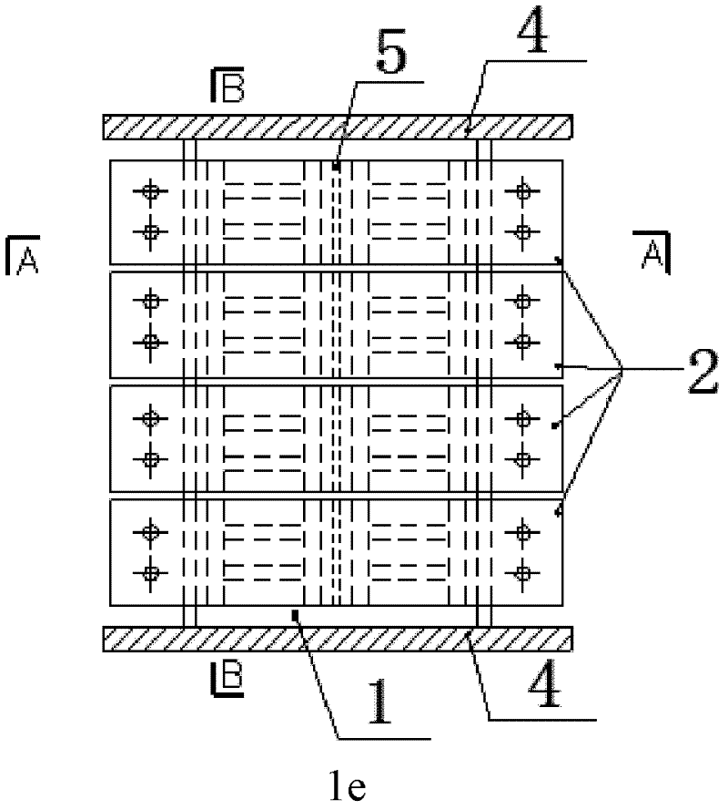
[0030] Such as figure 1 As shown in a, 2a and 3a, the figure includes the upper and lower horizontal connecting steel plates 4 arranged on the energy-dissipating steel plate 1, and the two sides of the energy-dissipating steel plate 1 are respectively provided with restraining devices 2, and the restraining device 2 and the energy-dissipating steel plate 1 are connected to each other Independently, the restraint devices 2 are horizontally arranged in pairs on both sides of the energy dissipation steel plate 1 without intersecting. A horizontal stiffener 5 is provided on one side of the energy dissipation steel plate 1 , and the stiffener 5 is welded horizontally on the energy dissipation steel plate 1 , parallel to and not in contact with the restraint device 2 . The left and right ends of the stiffener 5 are respectively welded to the flange plate. The restraint device 2 and the stiffener 5 constrain the energy-dissipating steel plate 1 to prevent out-of-plane buckling.

Embodiment 2

[0032] Such as figure 1 As shown in b, 2b and 3b, the figure includes the upper and lower horizontal connecting steel plates 4 arranged on the energy-dissipating steel plate 1, and the two sides of the energy-dissipating steel plate 1 are respectively provided with restraint devices 2, and the restraint device 2 and the energy-dissipating steel plate 1 are connected to each other. Independently, the restraint devices 2 are horizontally arranged in pairs on both sides of the energy dissipation steel plate 1 without intersecting. A vertical stiffener 5 is provided on one side of the energy-dissipating steel plate 1 , and the stiffening rib 5 is welded on the energy-dissipating steel plate 1 through its entire length, and is inside the restraint device 2 and does not connect with the restraint device 2 . The upper and lower ends of the stiffener 5 are respectively welded to the upper and lower horizontal connecting steel plates 4 . The restraint device 2 and the stiffener 5 cons...

Embodiment 3

[0034] Such as figure 1 As shown in c, 2c and 3c, the figure includes the upper and lower horizontal connecting steel plates 4 arranged on the energy-dissipating steel plate 1, and the two sides of the energy-dissipating steel plate 1 are respectively provided with restraining devices 2, and the restraining device 2 and the energy-dissipating steel plate 1 are connected to each other. Independently, the restraint devices 2 are horizontally arranged in pairs on both sides of the energy dissipation steel plate 1 without intersecting.

[0035] A horizontal stiffener 5 is provided on one side of the energy-dissipating steel plate 1, and the stiffening rib 5 is welded on the energy-dissipating steel plate 1 throughout its length, parallel to and not connected to the restraint device 2, and the left and right ends of the stiffening rib 5 are welded respectively on the flange. A vertical stiffener 5 is provided on the other side of the energy-dissipating steel plate 1, and the stiff...


PUM


Abstract

The invention discloses a metal damper provided with restraining devices and stiffening ribs. The metal damper comprises an energy consumption steel plate, horizontal connecting steel plates arranged above and below the energy consumption steel plate, wing edge plates arranged at two ends of the energy consumption steel plate as well as the stiffening ribs and the restraining devices which are arranged on two sides of the energy consumption steel plate, wherein the energy consumption steel plate is welded with the upper and low horizontal connecting steel plates; the energy consumption steel plate is welded with the wing edge plates at two ends of the energy consumption steel plate; the restraining devices are respectively arranged on two sides of the energy consumption steel plate; bolt holes are formed in the restraining devices; and the restraining devices on two sides of the energy consumption steel plate are fixedly connected by bolts. According to the metal damper disclosed by the invention, the energy consumption capability and the stability of the damper are ensured; no cross weld joints exist between the stiffening ribs on the same side of the energy consumption steel plate; the stiffening ribs can be arranged in a through way without being cut off and is convenient to weld; the welding quality is easy to ensure; and the restraining devices are independent from the energy consumption steel plate, so that the damage to the energy consumption steel plate as the welding of the stiffening ribs on the energy consumption steel plate is avoided.

Description

technical field [0001] The invention relates to the field of anti-seismic technology of building engineering structures, in particular to a building energy-dissipating metal damper provided with restraint devices and stiffeners. Background technique [0002] The energy dissipation and shock absorption of building structures refers to the installation of appropriate energy dissipation components in the building structure. The energy dissipation components can be composed of energy dissipation and shock absorption devices and supporting components such as braces, walls, beams or nodes. The metal energy dissipator is an energy-dissipating shock-absorbing device with superior energy-dissipating performance, simple structure, convenient manufacture, low cost and easy replacement. It can be used as an energy-dissipating unit or limiting device in conjunction with a seismic-isolation support or a seismic-isolation system, and it can also be used alone in a building structure as an ...

Claims


Application Information

Patent Timeline
Patent Type & Authority Applications(China)
IPC IPC(8): E04B1/98
Inventor 陈明中黄坤耀徐继东邓文艳
Owner SHANGHAI SAFE SEISMIC RETROFIT & VIBRATION CONTROL TECH
Learn More