50-ampere power consumption balanced-type high-power constant-current source
A high-power, constant-current source technology, applied in the direction of emergency protection circuit devices, instruments, and electric variables for limiting overcurrent/overvoltage, can solve the problem of short service life of power devices, insufficient maximum output current, and system Low reliability and other issues, to achieve the effect of reducing the number of components and reducing design costs
- Summary
- Abstract
- Description
- Claims
- Application Information
AI Technical Summary
Problems solved by technology
Method used
Image
Examples
Embodiment 1
[0026] Embodiment 1 illustrates the overall structure of the present invention in conjunction with the accompanying drawings
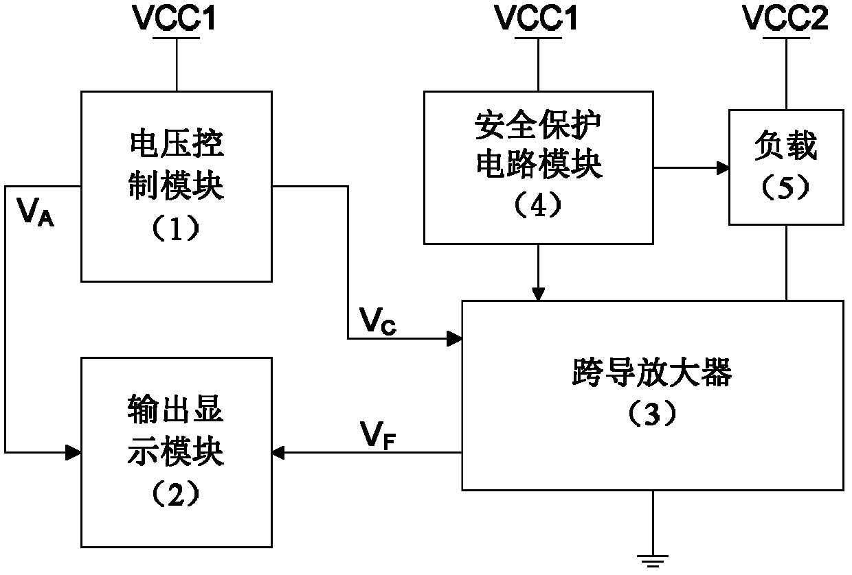
[0027] The present invention has a balanced power consumption high-power constant current source, and the structure includes: a voltage control module 1, an output display module 2, a transconductance amplifier 3, and a safety protection circuit module 4. The structural block diagram is as follows: figure 1 Shown, where the output port V of the voltage control module 1 C Connected to the transconductance amplifier 3, the required constant current signal is generated by the transconductance amplifier 3 to drive the load 5, and the safety protection circuit module 4 provides safety protection for the load. At the same time, the output port V of the voltage control module 1 A and the output port V of the transconductance amplifier module 3 F It is connected to the mode selection input terminal of the output display module 2, and the output display module...
Embodiment 2
[0028] Embodiment 2 Voltage Control Module 1
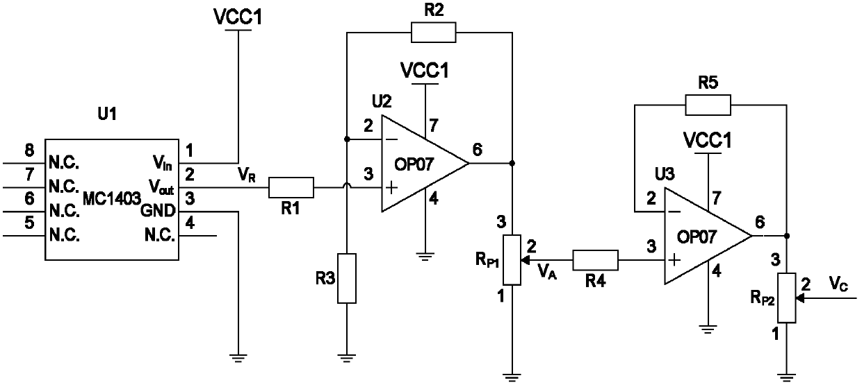
[0029] Such as figure 2 As shown, voltage control module 1 includes: pin 1 of voltage reference chip U1 (MC1403) is connected to power supply VCC1 (+15V, rated power 30W), pin 3 is grounded, and pin 2 is connected to single operational amplifier U2 (OP07) through resistor R1 (15kΩ). ), pin 4 of the single op amp U2 (OP07) is grounded, pin 7 is connected to the power supply VCC1 (+15V, rated power 30W), pin 2 is grounded through the resistor R3 (30kΩ), and pin 2 of the single op amp U2 (OP07) is grounded. The pin is connected to the 6 pin of the single op amp U2 (OP07) through the resistor R2 (30kΩ), and the 6 pin of the single op amp U2 (OP07) is connected to the potentiometer R p1 (100kΩ) pin 3, potentiometer R p1 (100kΩ) pin 1 is grounded, and pin 2 is connected to the output port V of voltage control module 1 A , the output port V A Connect to the mode selection input terminal of the output display module 2, and the potent...
Embodiment 3
[0030] Embodiment 3 Transconductance amplifier 3
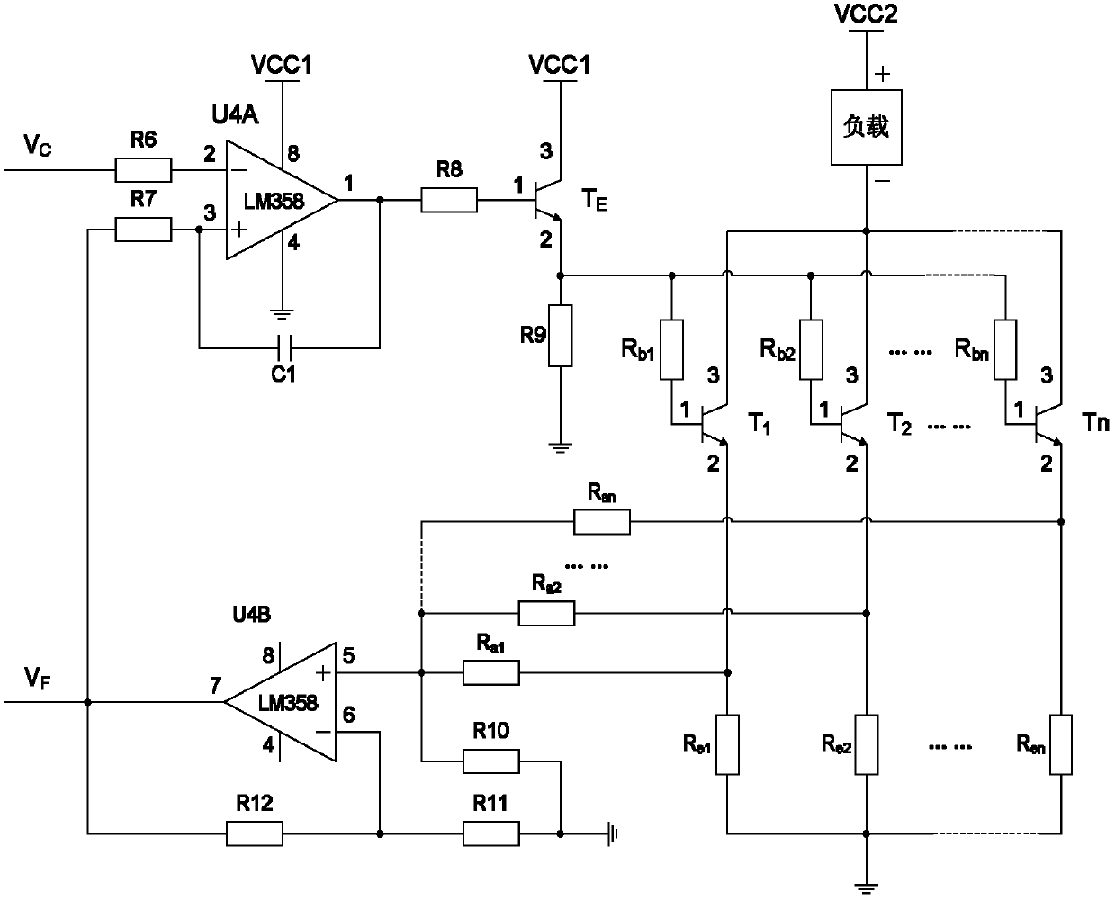
[0031] Such as image 3 As shown, the transconductance amplifier 3 includes: the 4-pin of the dual operational amplifier U4A (LM358) is grounded, the 8-pin is connected to the power supply VCC1 (+15V, rated power 30W), and the 2-pin is connected to the output of the voltage control module 1 through the resistor R6 (10kΩ) Port V C , connected to the control signal output port of the soft-start protection circuit in the safety protection circuit module 4, and pin 3 is connected to the output port V of the transconductance amplifier 3 through a resistor R7 (10kΩ) F At the same time, pin 3 of the dual op amp U4A (LM358) is connected to pin 1 of the dual op amp U4A (LM358) through a capacitor C1 (4.7μF), and pin 1 of the dual op amp U4A (LM358) is connected to N-type via a resistor R8 (1kΩ). Darlington Power Transistor T E (TIP132) pin 1, N-type Darlington power transistor T E (TIP132) pin 3 is connected to power supply VCC1 (+...
PUM
 Abstract
Description
Claims
Application Information
 - R&D
- Intellectual Property
- Life Sciences
- Materials
- Tech Scout
- Unparalleled Data Quality
- Higher Quality Content
- 60% Fewer Hallucinations
Browse by: Latest US Patents, China's latest patents, Technical Efficacy Thesaurus, Application Domain, Technology Topic, Popular Technical Reports.
© 2025 PatSnap. All rights reserved.Legal|Privacy policy|Modern Slavery Act Transparency Statement|Sitemap|About US| Contact US: help@patsnap.com


