Horizontal convection fan and frame seat thereof

A convection fan, horizontal technology, applied in the direction of non-variable pumps, non-volume pumps, radial flow pumps, etc., can solve the problems of reducing air intake, air turbulence, air volume and air pressure reduction, and achieve reduction Reverse air flow, concentrated air volume, avoiding turbulence

Active Publication Date: 2012-08-15
SUNONWEALTH ELECTRIC MACHINE IND
View PDF5 Cites 2 Cited by
  • Summary
  • Abstract
  • Description
  • Claims
  • Application Information

AI Technical Summary

Problems solved by technology

[0003] However, the air inlet side 913 and the air outlet side 914 of the prior art horizontal convection fan are only separated by a splitter 915, so that the air inlet side 913 and the air outlet side 914 are too close, and the air inlet side 913 and the air outlet side 914 are too close. There is no other design for separating the airflow between the air outlet sides 914, so the air blown out through the air outlet side 914 is easily affected by the suction force of the air inlet side 913, especially the air outlet side 914 adjacent to the splitter 915. The air is more likely to form a reverse air flow area (Z) due to the suction effect of the air inlet side 913, and the air in the reverse air flow area (Z) will be biased towards the air inlet side 913, and will be sucked back by the fan wheel 92 , not only causes the exhaust air volume of the air outlet side 914 to decrease, but also the air sucked back easily pushes against the air inhaled by the air inlet side 913 to cause turbulence, which in turn affects the smooth air suction of the air inlet side 913 performance, reduce its air intake
Moreover, the air outlet side 914 of the prior art frame seat 91 is almost completely open, so that the air blown out by the air outlet side 914 is easy to diffuse toward the surroundings, so the air cannot be concentrated and the air volume and air pressure are likely to decrease.

Method used


Image

  • Horizontal convection fan and frame seat thereof
  • Horizontal convection fan and frame seat thereof
  • Horizontal convection fan and frame seat thereof

Examples


Embodiment Construction

[0054] In order to make the above-mentioned and other objects, features and advantages of the present invention more comprehensible, the preferred embodiments of the present invention are specifically cited below, together with the accompanying drawings, and are described in detail as follows:

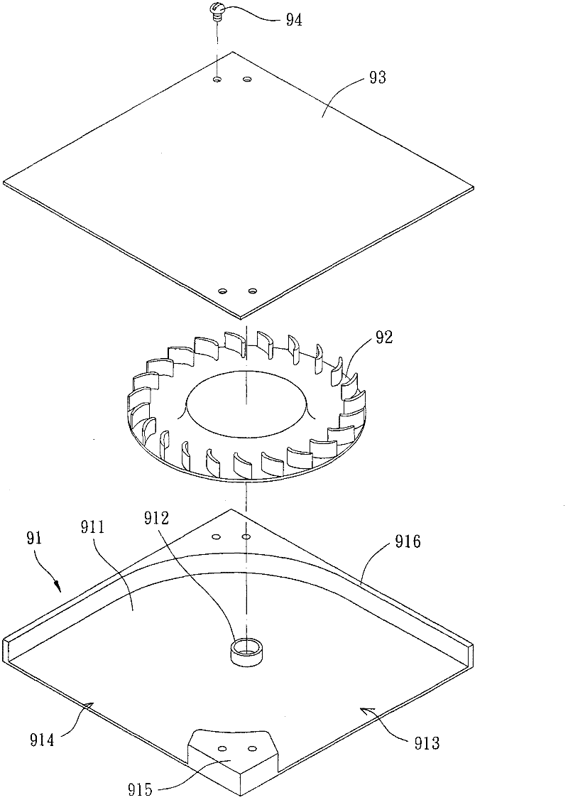
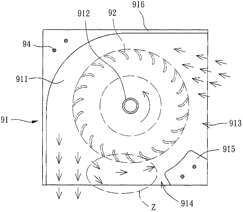
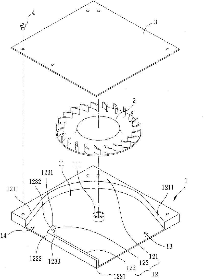
[0055] Please refer to image 3 and Figure 4 As shown, the horizontal convection fan according to the first embodiment of the present invention includes a frame base 1 , a fan wheel 2 and a cover plate 3 . Wherein, the fan wheel 2 and the cover plate 3 are both arranged on the frame base 1, the fan wheel 2 is located between the frame base 1 and the cover plate 3, and can rotate to drive air circulation.

[0056] The frame seat 1 has a bottom plate 11 and a side wall 12 . One surface of the bottom plate 11 is provided with a shaft seat 111, the side wall 12 is formed on the surface of the bottom plate 11 provided with the shaft seat 111, and is located at the outer periphery of the ...


PUM


Abstract

The invention discloses a horizontal convection fan which comprises a frame seat, a fan wheel and a cover plate, wherein the frame seat is provided with an axle seat on a bottom plate; the axle seat is rotatably provided with the fan wheel; the bottom plate is provided with a side wall on the peripheral edge of the axle seat; the side wall is provided with a flow guide part, an obstructing part and a shunting part; a wind inlet is formed between the flow guide part and the obstructing part; a wind outlet is formed between the flow guide part and the shunting part; the obstructing part is provided with a first end adjacent to the wind inlet, and a second end facing the air outlet; the shunting part is arranged on the second end; and the cover plate is arranged on the top surface of the side wall of the frame seat. According to the horizontal convection fan, the reverse airflow of the horizontal convection fan can be reduced by the obstructing part and the shunting part, and turbulent flow is avoided.

Description

technical field [0001] The invention relates to a horizontal convection fan and its frame seat, in particular to a horizontal convection fan with radial air inlet and outlet and its frame seat. Background technique [0002] Please refer to figure 1 and figure 2 As shown, the prior art horizontal convection fan structure includes a frame seat 91 , a fan wheel 92 and a cover plate 93 . The frame seat 91 has a bottom plate 911, on which a shaft seat 912 is arranged, and two adjacent sides of the bottom plate 911 are respectively an air inlet side 913 and an air outlet side 914, and the air inlet side 913 and the air outlet side are respectively The wind side 914 is partitioned by a splitter 915 , and a side wall 916 extends from the bottom plate 911 , and two ends of the side wall 916 are respectively connected to the wind inlet side 913 and the wind outlet side 914 . The fan wheel 92 is rotatably disposed on the shaft seat 912 . The cover plate 93 is disposed on the frame...

Claims


Application Information

Patent Timeline
Patent Type & Authority Applications(China)
IPC IPC(8): F04D17/08F04D29/44
CPCF04D17/04F04D29/4226
Inventor 周文南施毓伦
Owner SUNONWEALTH ELECTRIC MACHINE IND
Why Eureka
Try Eureka