
Sump dredging system and mode

A technology for water collection wells and dredging devices, which is applied in waterway systems, water supply devices, cleaning sewer pipes, etc., can solve the problems of not being able to select submersible sewage pumps, not being able to select sewage pumps, and high drainage head, and achieve a wide range of applications. Avoid secondary pollution, less equipment and less investment

Active Publication Date: 2012-08-15
POWERCHINA HUADONG ENG COPORATION LTD
View PDF4 Cites 5 Cited by
  • Summary
  • Abstract
  • Description
  • Claims
  • Application Information

AI Technical Summary

Problems solved by technology

[0005] Considering the safety point of view of current hydropower station design, the position of the outlet of the drainage pipe is at a higher position, especially for a relatively large-scale power station or pumping station, the volume and depth of the water collection well are larger, and the selection of larger Capacity and high lift sewage pumps are difficult, and even in some cases, it is impossible to choose a suitable submersible sewage pump
However, the water collection wells in some areas of the power station, such as the water collection wells in dams and pad ponds, are relatively far away from the pressurized water source and compressed air source, so it is more difficult to set them up separately, and the drainage head is relatively high, and they cannot be selected. Suitable type of sewage pump

Method used


Image

  • Sump dredging system and mode
  • Sump dredging system and mode
  • Sump dredging system and mode

Examples


Embodiment Construction

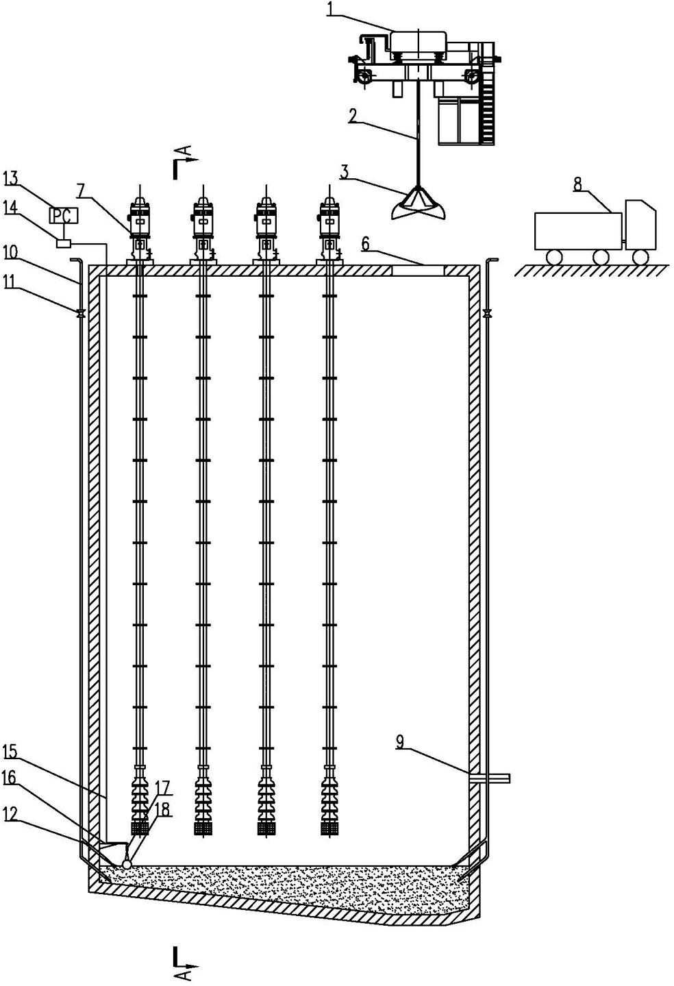
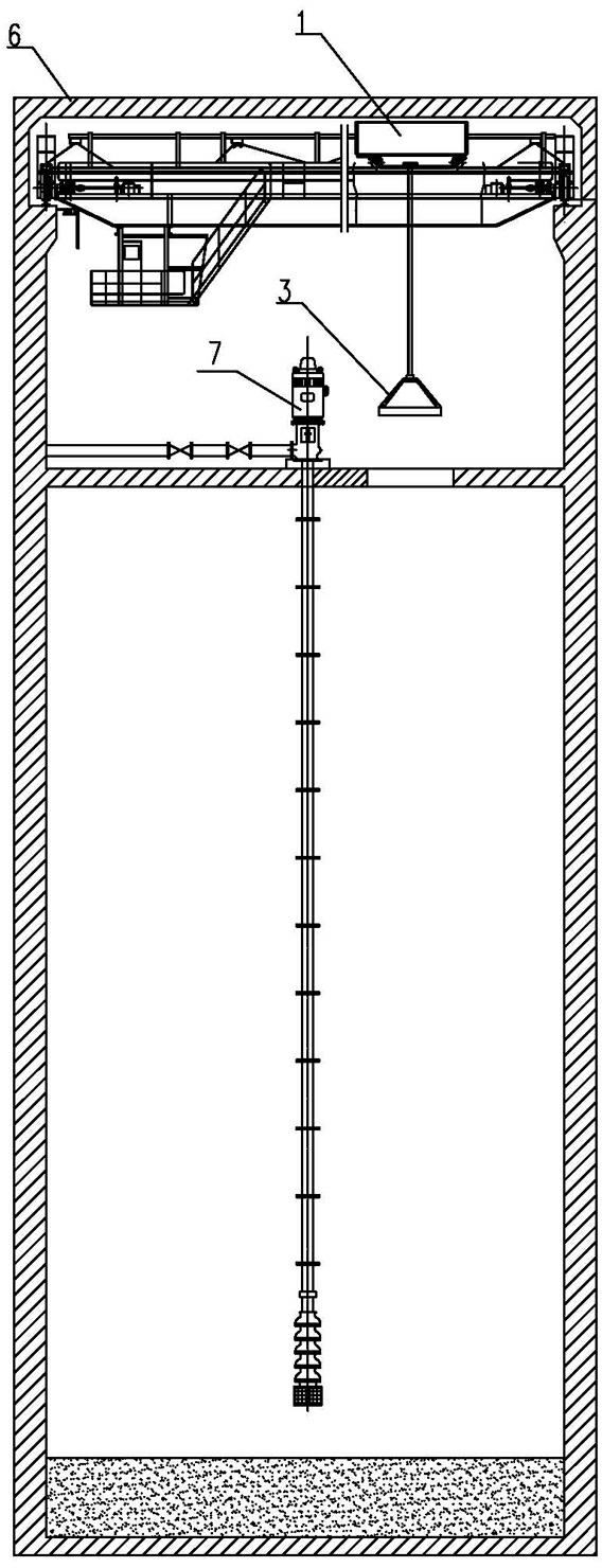
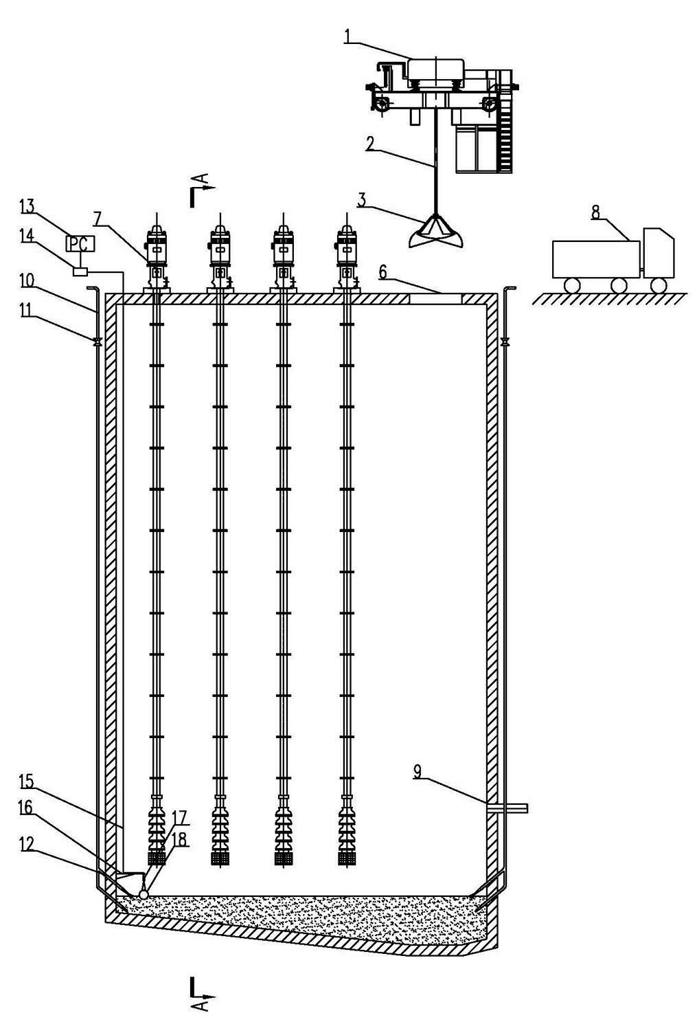
[0023] Such as figure 1 , figure 2 As shown, the present embodiment is a new type of water collection well dredging system, in which drainage facilities 7 are installed in the water collection well 6, and the bottom plate of the water collection well is made at an appropriate angle of inclination (that is, one area of ​​the bottom plate of the water collection well is lower, and the rest of the bottom plate The area is inclined at a certain angle with this area, which is convenient to concentrate the sediment in the water collection well in this area), and the sandy water flow collection pipe 9 is buried near the lower area of ​​the bottom of the water collection well. Install a grab-type dredging device above the water collection well and at the lowest point corresponding to the bottom plate. In this embodiment, a sediment density and sediment height measurement system and a sediment collection high-pressure flushing system are also set at the bottom of the water collection...


PUM


Abstract

The invention relates to a sump dredging system and a sump dredging mode. The invention aims at providing the sump dredging system and the sump dredging mode with the advantages of convenience for operation, less energy consumption and high efficiency. The technical scheme is as follows: the sump dredging system is characterized in that a sump is internally provided with a drainage facility, a sand-containing water flow collecting pipe is buried in a place close to a lower region on the bottom of the sump; a bottom plate of the sump is provided with a slope with certain inclination, a grab bucket type dredging device is arranged above the sump and corresponding to the lowest part of the bottom plate; and a sediment density and sediment accumulation height measurement system and a sediment collection high-pressure washing system are arranged at the bottom of the sum. The sump dredging system and the sump dredging mode are suitable for water and electricity and water conservancy projects, especially suitable for dredging sediments on the bottom of a sump in an underground power plant, a dam body and a plunge pool, dredging sediments on the bottom of the sump of a water pumping pump station, and is also suitable for regions such as water taking pools of various diversion works and sedimentation basins of a sewage treatment plant.

Description

technical field [0001] The invention relates to a water collection well dredging system and a dredging method thereof. It is suitable for hydropower and water conservancy projects, especially for the cleaning of the sediment at the bottom of the sump well in the underground powerhouse of the hydropower station, the dam body and the water cushion pond, and the cleaning of the sediment at the bottom of the sump well of the pumping station. It is also suitable for the water diversion project Intake ponds and sedimentation ponds of sewage treatment plants and other areas. Background technique [0002] Hydropower stations and pumping stations are generally equipped with water collection wells for discharging leakage water from workshops and units, and some are also provided with water collection wells for maintenance and drainage of units. The curtain grouting around the plant during the construction period may cause a large amount of mud to seep into the water collection well. ...

Claims


Application Information

Patent Timeline
IPC IPC(8): E02F3/47E03F9/00
Inventor 李胜兵方杰袁静方晓红周杰
Owner POWERCHINA HUADONG ENG COPORATION LTD
Learn More