
Support frame structure of seeding devices

A sowing device and support frame technology, which is applied in the field of support frame structure, can solve the problems of spending more time for planting, using agricultural machines, and slow sowing speed, etc.

Inactive Publication Date: 2012-08-15
吴鸿基
View PDF6 Cites 0 Cited by
  • Summary
  • Abstract
  • Description
  • Claims
  • Application Information

AI Technical Summary

Problems solved by technology

[0002] Generally, the seeder 1 used for sowing is mostly a special machine with a single sowing function, and cannot be used with agricultural machines for other purposes. Please refer to figure 1 As shown, the seeder 1 is mainly provided with a driving device 10, and a seeding device 12 is arranged on the support 11 of the seeder 1, and the wheel 13 of the seeder 1 is driven to advance through the operation of the driving device 10, thereby driving the seeding device 12 to operate. To achieve the action of sowing, but the general sowing device 12 is fixed on a single body and cannot be assembled on agricultural machines of different purposes. Therefore, it is necessary to purchase a special sowing machine for this kind of single sowing purpose, and it is necessary to spend more to purchase different machines. The cost of planting (such as seeders, intertillage management machines, shredder weeders, etc., etc.), and the seeder can only sow in a single row at a time, the sowing speed is relatively slow, and it takes more time to sow, and It is impossible to accurately set the distance between two seeding rows; therefore, in view of the above-mentioned deficiencies in the existing seeder, the inventor devoted himself to research and improvement, and was able to create the present invention for the first time.

Method used


Image

  • Support frame structure of seeding devices
  • Support frame structure of seeding devices
  • Support frame structure of seeding devices

Examples


Embodiment Construction

[0014] Relevant present invention is for reaching above-mentioned purpose of use and effect, the technical means that adopts, presents preferred feasible embodiment hereby, and cooperates as shown in the accompanying drawings, detailed description is as follows:

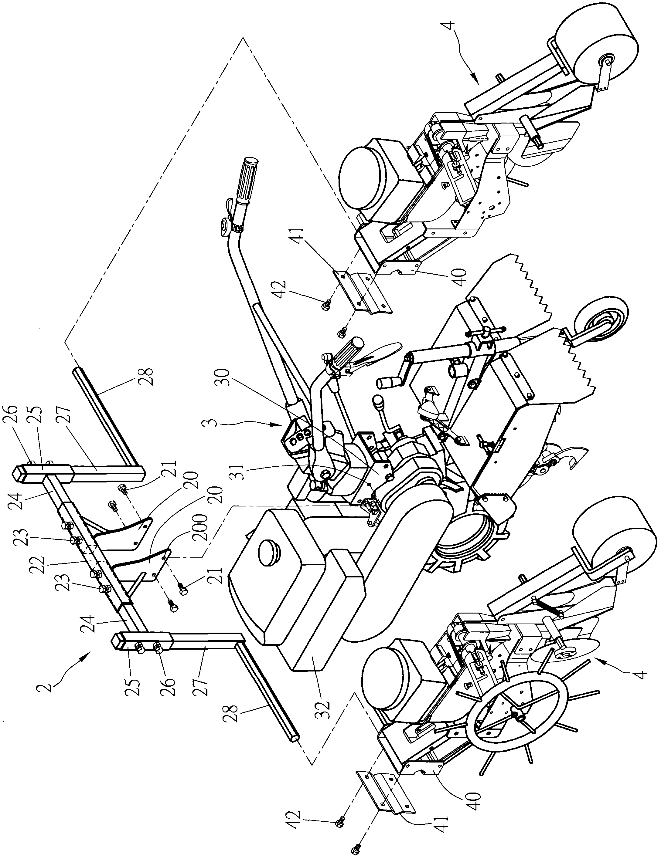
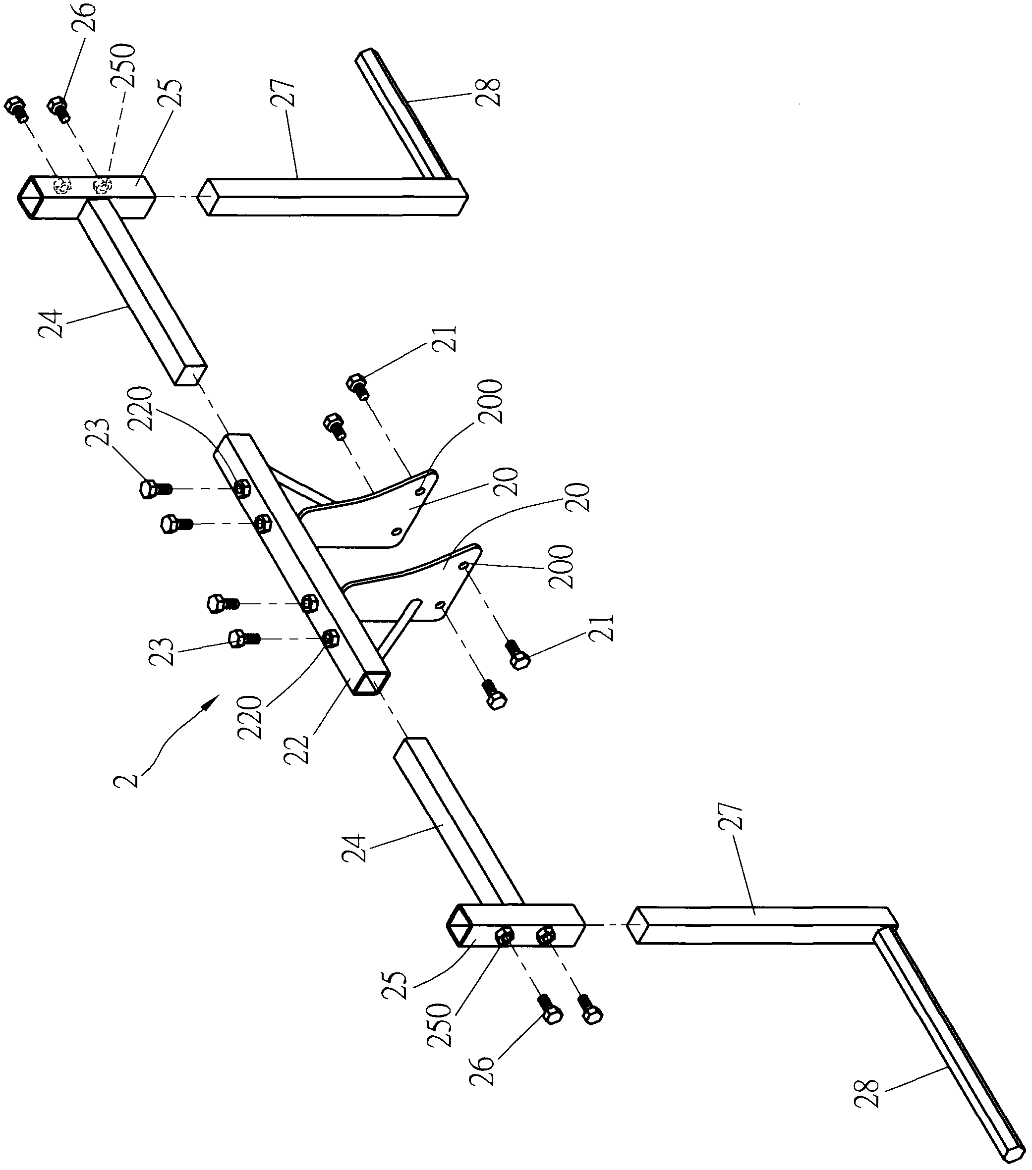
[0015] For an example of the invention, see figure 2 , image 3 , Figure 4 As shown, a support frame 2 is mainly provided, and the support frame 2 is set on the fixed seat 30 of any agricultural machine 3, and a group of seeding devices 4 are respectively assembled at the two ends of the support frame 2. The support frame 2 (such as image 3 Shown) are provided with two fixing seats 20 oppositely, are provided with several perforations 200 for threaded fixing element 21 on the fixing seats 20, are provided with several screw holes 31 on the fixing seats 30 of the farming machine 3, by virtue of the multiple A screw fixing element 21 is passed through the perforation 200 on the fixing seat 20 of the support frame...


PUM


Abstract

The invention provides a support frame structure of seeding devices. The structure is mainly characterized in that a support frame is assembled on any one farming machine; at least a seeding device is arranged on the support frame; the support frame is provided with fixed bases; through holes for bolting components to pass are arranged on the fixed bases; the fixed bases of the support frame are fixedly arranged on a fixed base of the farming machine by the bolting components; and at least a support rod for assembling the seeding devices is arranged on the support frame. The structure has the following beneficial effects that at least a seeding device can be fixed on various farming machines with different purposes by the support frame, without additionally purchasing the special machine for seeding with single seeding purpose, thus the cost of purchasing various machines can be saved and the seeding devices are quite convenient to assemble.

Description

technical field [0001] The invention relates to a support frame structure of a seeding device, in particular to a structure capable of assembling at least one group of seeding devices on any farming machine, which saves the cost of purchasing a special machine and achieves the effect of convenient and fast sowing. Background technique [0002] Generally, the seeder 1 used for sowing is mostly a special machine with a single sowing function, and cannot be used with agricultural machines for other purposes. Please refer to figure 1 As shown, the seeder 1 is mainly provided with a driving device 10, and a seeding device 12 is arranged on the support 11 of the seeder 1, and the wheel 13 of the seeder 1 is driven to advance through the operation of the driving device 10, thereby driving the seeding device 12 to operate. To achieve the action of sowing, but the general sowing device 12 is fixed on a single body and cannot be assembled on agricultural machines of different purposes...

Claims


Application Information

Patent Timeline
Patent Type & Authority Applications(China)
IPC IPC(8): A01C7/18
Inventor 吴鸿基
Owner 吴鸿基
Learn More