
A manual drive mechanism of off-excitation tap changer

A tap changer, manual drive technology, applied in the contact drive mechanism, transformer, electrical components, etc., can solve the problems of inconvenient shift of transformer gear, complicated mechanism, broken gear of the last stage, etc., and achieve a simple structure of manual mechanism. , The effect of reducing manufacturing cost and convenient manufacturing and installation

Active Publication Date: 2015-11-04
SHANGHAI HUAMING POWER EQUIP CO LTD +1
View PDF5 Cites 1 Cited by
  • Summary
  • Abstract
  • Description
  • Claims
  • Application Information

AI Technical Summary

Problems solved by technology

[0002] For many years, the transformer cage off-excitation tap-changer has used a manual mechanism that requires 33 turns of the tap-changer to change one gear. The number of turns of the tap-changer to change one gear is too many. On the other hand, the gear position indicator plate of the original manual mechanism is rotated by the hand-operated input shaft through the multi-stage deceleration of the cylindrical gear, and the gear position of the indicator plate is generally made into 12 equal divisions. The speed ratio from the input shaft to the gear indicator disc shaft is (33×12)396:1, which requires multi-stage deceleration, and the mechanism is complicated; the gear modulus is very small, only M1, and the mechanism also requires that after reaching the limit gear. limit function
In this way, the shifting operator may shake the last gear without obvious feeling. Practice has also proved that such accidents often occur.

Method used


Image

  • A manual drive mechanism of off-excitation tap changer
  • A manual drive mechanism of off-excitation tap changer
  • A manual drive mechanism of off-excitation tap changer

Examples


Embodiment Construction

[0028] The following examples further describe the present invention, but the examples are only for illustrating the present invention rather than limiting the present invention.

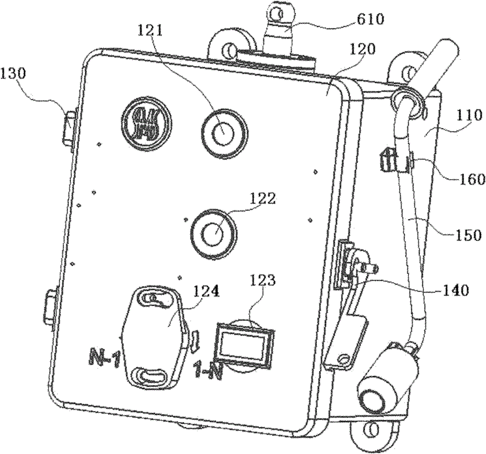
[0029] see figure 1 The manual drive mechanism for off-circuit tap-changers shown can be used for cage-type off-circuit tap-changers and can also be used for drum-type off-circuit tap-changers.

[0030] The manual drive mechanism of the off-excitation tap changer includes a box body 110 and a box cover 120 , one side of the box cover 120 is hinged with the box body 110 through a hinge mechanism 130 , and the other side is connected with the box body 110 through a door lock 140 . The structure of the box body 110 and the box cover 120 of the present invention is basically similar to the box body and the box cover structure of the existing manual drive mechanism. In order to facilitate manual operation, observe the gear position, manual position and shift count, a manual operation hole (below the cov...


PUM


Abstract

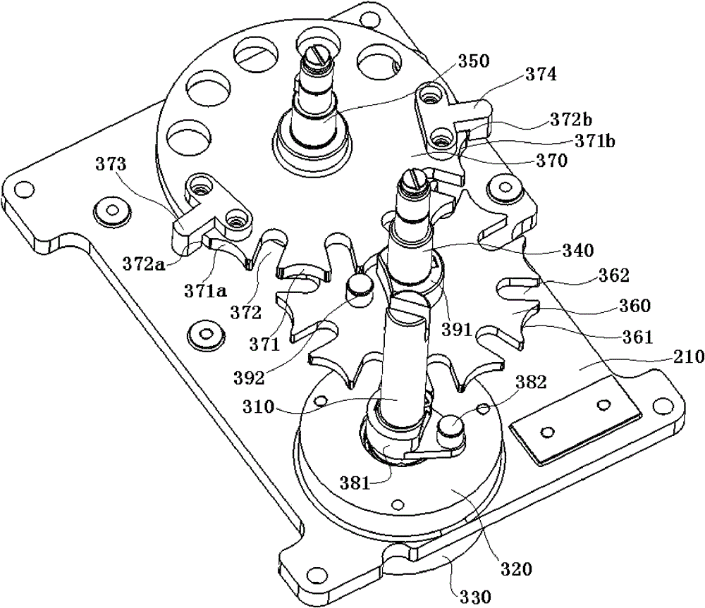
The invention discloses a manual driving mechanism of an off-circuit tap-changer. An input terminal of a two-stage sheave deceleration transmission mechanism of an internal transmission mechanism possesses a hand crank rotation shaft. A hand position indicator dial is fixed on a first stage output shaft of the two-stage sheave deceleration transmission mechanism and rotates with the first stage output shaft synchronously. A gear indicator dial is fixed on a second stage output shaft of the two-stage sheave deceleration transmission mechanism and rotates with the second stage output shaft synchronously. A main transmission output shaft is shaftingly arranged in a box. An output terminal of the main transmission output shaft extends out of the box, and the input terminal and the hand crank rotation shaft form power connection through a bevel gear pair. By using the mechanism of the invention, shift operation of a transformer tap-changer is convenient. The tap-changer can change 1shift only through rotating of 10 laps. Hand-operated force and a number of laps are moderate. The mechanism of the invention is fully functional and possesses functions of cutting off electricity through inserting the hand crank, observing an operation signal, detecting an in-gear signal, recording shifting counting and the like.

Description

Technical field: [0001] The invention relates to the technical field of a transformer tap changer, in particular to a manual drive mechanism for an off-excitation tap changer. Background technique: [0002] For many years, the transformer cage off-excitation tap-changer has used a manual mechanism that requires 33 turns of the tap-changer to change one gear. The number of turns of the tap-changer to change one gear is too many. On the other hand, the gear position indicator plate of the original manual mechanism is rotated by the hand-operated input shaft through the multi-stage deceleration of the cylindrical gear, and the gear position of the indicator plate is generally made into 12 equal divisions. The speed ratio from the input shaft to the gear indicator disc shaft is (33×12)396:1, which requires multi-stage deceleration, and the mechanism is complicated; the gear modulus is very small, only M1, and the mechanism also requires that after reaching the limit gear. To li...

Claims


Application Information

Patent Timeline
Patent Type & Authority Patents(China)
IPC IPC(8): H01H3/32H01H1/56H01F29/02
Inventor 肖日明
Owner SHANGHAI HUAMING POWER EQUIP CO LTD
Learn More