
Pipeline quick-mounting and quick-dismounting connection assembly

A technology for connecting components and pipes, applied in mechanical equipment, couplings, etc., can solve the problems of time-consuming connection methods, weight reduction of pipe joint connections, and increased weight of pipeline systems, etc., to achieve the effect of convenient opening and inspection, and prolonging service life.

Active Publication Date: 2012-08-01
AEROSPACE PRECISION PROD INC LTD
View PDF10 Cites 4 Cited by
  • Summary
  • Abstract
  • Description
  • Claims
  • Application Information

AI Technical Summary

Problems solved by technology

First, special equipment is required for the flared connection between the piping system and the sleeve, which is cumbersome and unstable. When the pipe wall is thicker, the flared connection with the sleeve is even more unstable
The second is that it takes a long time to install or disassemble and repair using pipe joints
The third is that the weight of the pipe joint connection is reduced, which increases the weight of the pipeline system
[0004] Welding method: welding is carried out when the pipe is connected. Although this method can realize the pipe connection, it has many disadvantages
First, it requires a large operating space during welding, which is not suitable for pipe connections in small spaces
Second, it is difficult to guarantee the sealing after welding
Third, the welding operation time is longer
Fourth, disconnection inspection cannot be carried out after welding. If inspection is required, it must be forcibly sawn open. After inspection, welding is performed. It is more difficult to ensure the sealing of the secondary welding and may cause the risk that the pipeline system is too short to be reconnected.
[0005] Therefore, the current connection method of the pipeline system is time-consuming, the sealing is not reliable, and it is troublesome to update and repair

Method used


Image

  • Pipeline quick-mounting and quick-dismounting connection assembly
  • Pipeline quick-mounting and quick-dismounting connection assembly
  • Pipeline quick-mounting and quick-dismounting connection assembly

Examples


Embodiment Construction

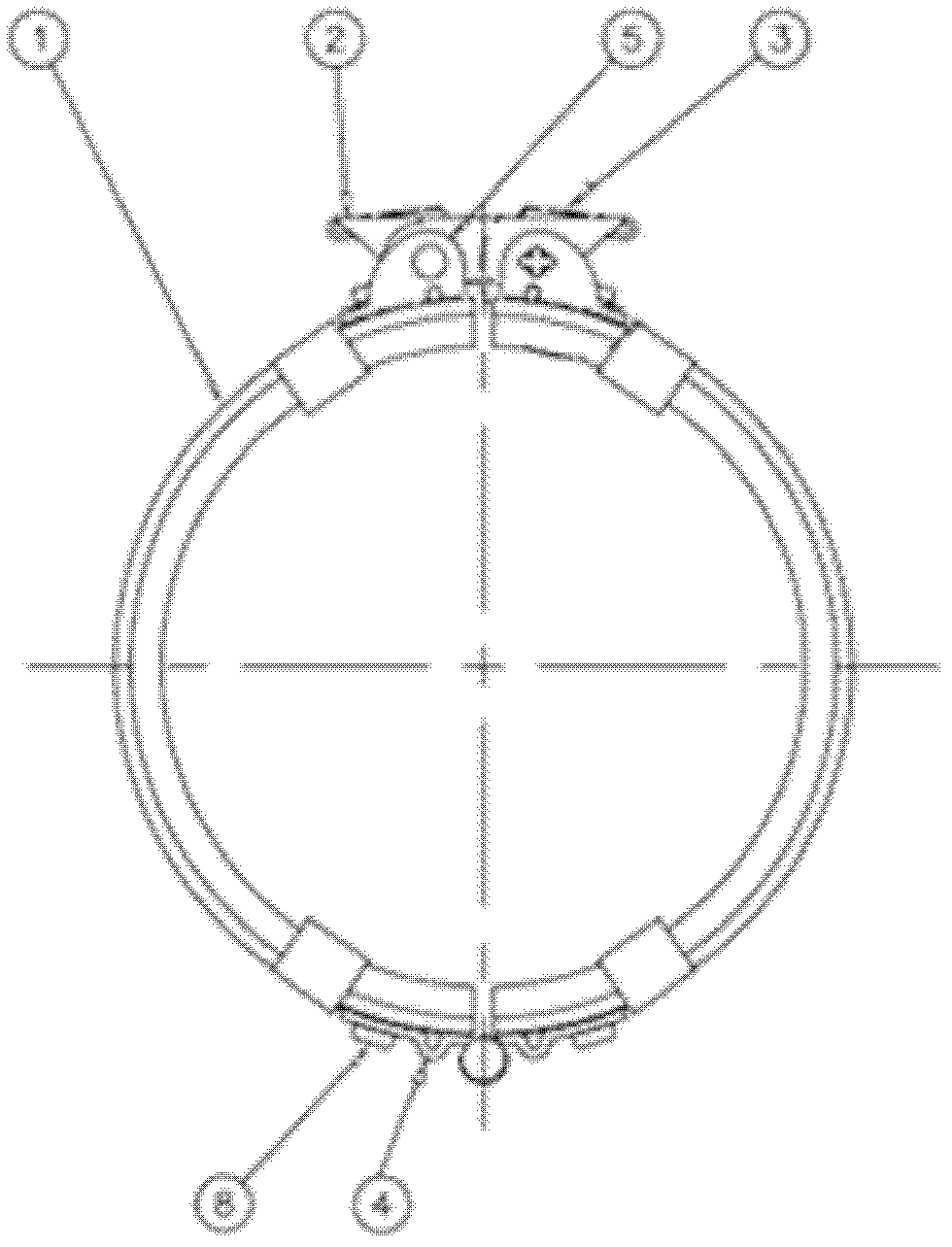
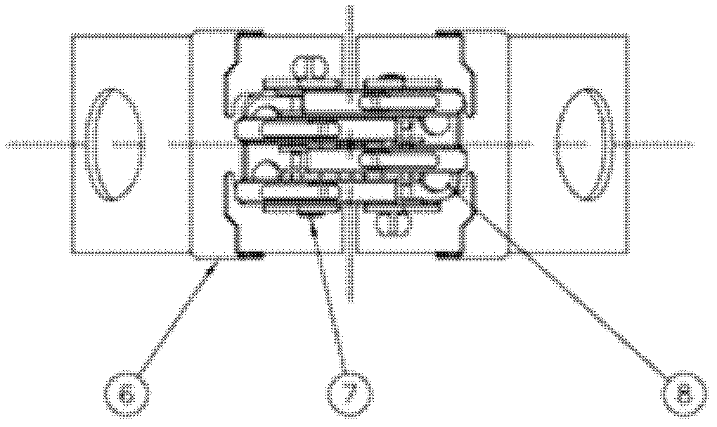
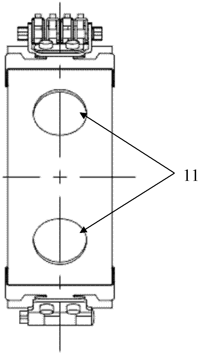
[0028] like Figure 1 to Figure 4 As shown, the present invention includes two semicircular retaining rings 1, one end of the two retaining rings 1 is hinged together by a hinge 4, and an axle seat 5 is fixedly installed on the outer side of the end of the other end, and each axle seat is fixed on each axle seat. A mandrel 7 is provided, and each mandrel 7 is respectively provided with at least one lock plate connected with the mandrel rotation through the shaft hole. There is a hook end, and there is a gap between the lock piece and the lock piece and between the lock piece and the shaft seat, exposing the shaft body of the mandrel, and the hook end can be hooked on the corresponding shaft body of another mandrel.

[0029] In order to prevent the locking piece from popping up automatically and causing the hook to be decoupled from the mandrel, an elastic back pressure device is also provided to prevent the locking piece from bouncing up and causing the hook to be disengaged f...


PUM


Abstract

The invention provides a pipeline quick-mounting and quick-dismounting connection assembly. The pipeline quick-mounting and quick-dismounting connection assembly comprises two half round protection rings, wherein one end of each of the two protection rings is mutually hinged; a shaft seat is fixedly mounted on the outer side of the end head of the other end of each of the two protection rings respectively; a mandrel is fixedly mounted on each of the shaft seats respectively; at least one lock sheet rotationally connected with the mandrel through shaft holes is arranged on each of the mandrels; a hanger end is also arranged on the lock sheet; and the hanger end can be hooked on a corresponding mandrel body of another mandrel. The pipeline quick-mounting and quick-dismounting connection assembly has the benefits as follows: the lock sheets are lifted up to loosen the protection rings; the connection assembly is controlled to be clamped or loosened by controlling the hangers of the lock sheets to be hooked or unhooked with the mandrels; and compared with the prior art, the connection assembly is convenient to open and check without any auxiliary tool, the mounting, debugging or checking time is shortened, and the service life of the connection assembly is prolonged.

Description

technical field [0001] The invention relates to a tool for connecting pipes, in particular to a pipe connecting assembly capable of quick connection and installation as well as quick disassembly and separation. Background technique [0002] Pipeline system connections generally use pipe joints and pipe welding. [0003] The way of using pipe joints: first, the pipe is flared and installed on the pipe sleeve through special equipment, and then the connection of the pipe system is realized through the connection between the pipe sleeve and the pipe joint assembly. This method has the advantage of checking the pipe joint position More convenient, but more disadvantages. One is that the flaring connection between the pipeline system and the pipe sleeve needs to adopt special equipment, which is troublesome and unstable. When the pipe wall thickness is thicker, the flaring connection with the pipe sleeve is even more unstable. The second is that it takes a long time to install ...

Claims


Application Information

Patent Timeline
Patent Type & Authority Applications(China)
IPC IPC(8): F16L37/12
Inventor 唐伟王光富何昌福
Owner AEROSPACE PRECISION PROD INC LTD
Learn More