Position regulating mechanism of main transmission box of backpack corn harvester

A technology of corn harvester and adjustment mechanism, which is applied in the field of agricultural machinery, and can solve the problems of inconvenient installation of knapsack corn harvester and four-wheel tractor, inability to connect main transmission box and power output shaft, production difficulties of knapsack corn harvester, etc. problems, to achieve the effect of increasing matching adaptability, simple and convenient adjustment, and simple structure

Inactive Publication Date: 2012-08-01
萝北县新利民农业机械制造有限公司
View PDF0 Cites 0 Cited by
  • Summary
  • Abstract
  • Description
  • Claims
  • Application Information

AI Technical Summary

Problems solved by technology

[0002] Due to the large number of manufacturers of medium and small power four-wheel tractors in my country, the product models produced are complicated and the structures are different, which makes it inconvenient to install the knapsack corn harvester with the four-wheel tractor, that is, a knapsack corn harvester can only be used with One type of four-wheel tractor is installed as a complete set, and the degree of generalization is greatly reduced, especially the positions of the power output shafts on the rear of various types of four-wheel tractors are different, and the main transmission boxes on the existing backpack corn harvesters of many varieties cannot The adjustment of the position resulted in the failure of the connection between the main transmission box and the power output shaft, and the knapsack corn harvester could not be installed on this type of four-wheel tractor. Production brings difficulties

Method used


Image

  • Position regulating mechanism of main transmission box of backpack corn harvester
  • Position regulating mechanism of main transmission box of backpack corn harvester
  • Position regulating mechanism of main transmission box of backpack corn harvester

Examples


Embodiment Construction

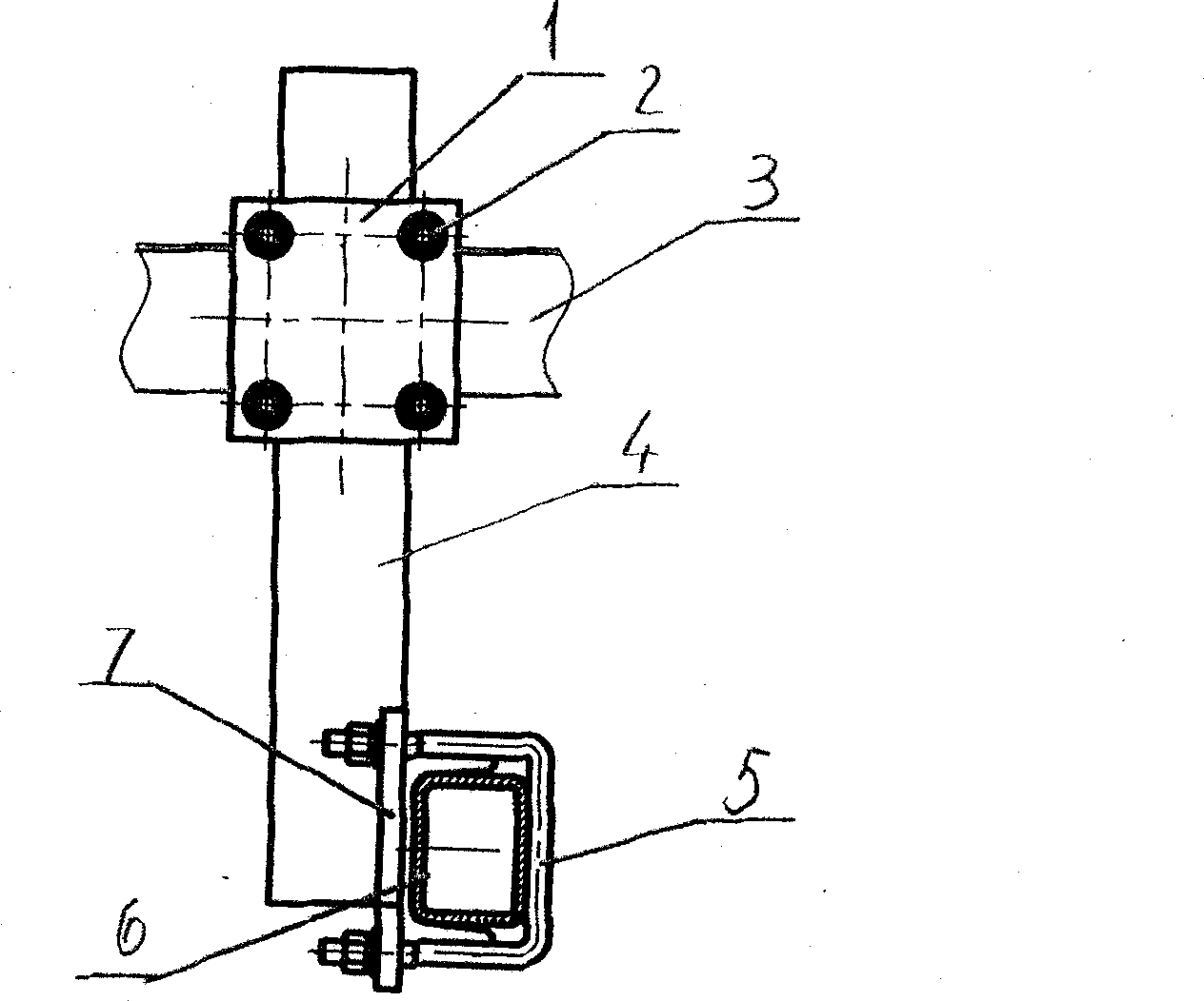
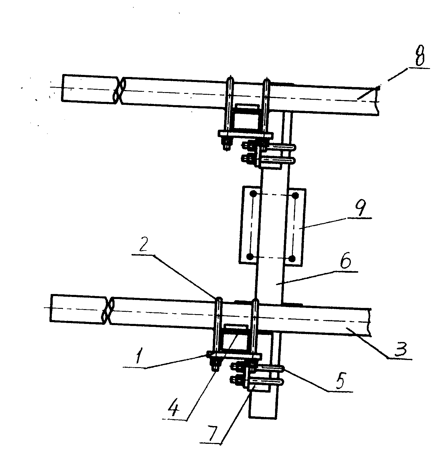
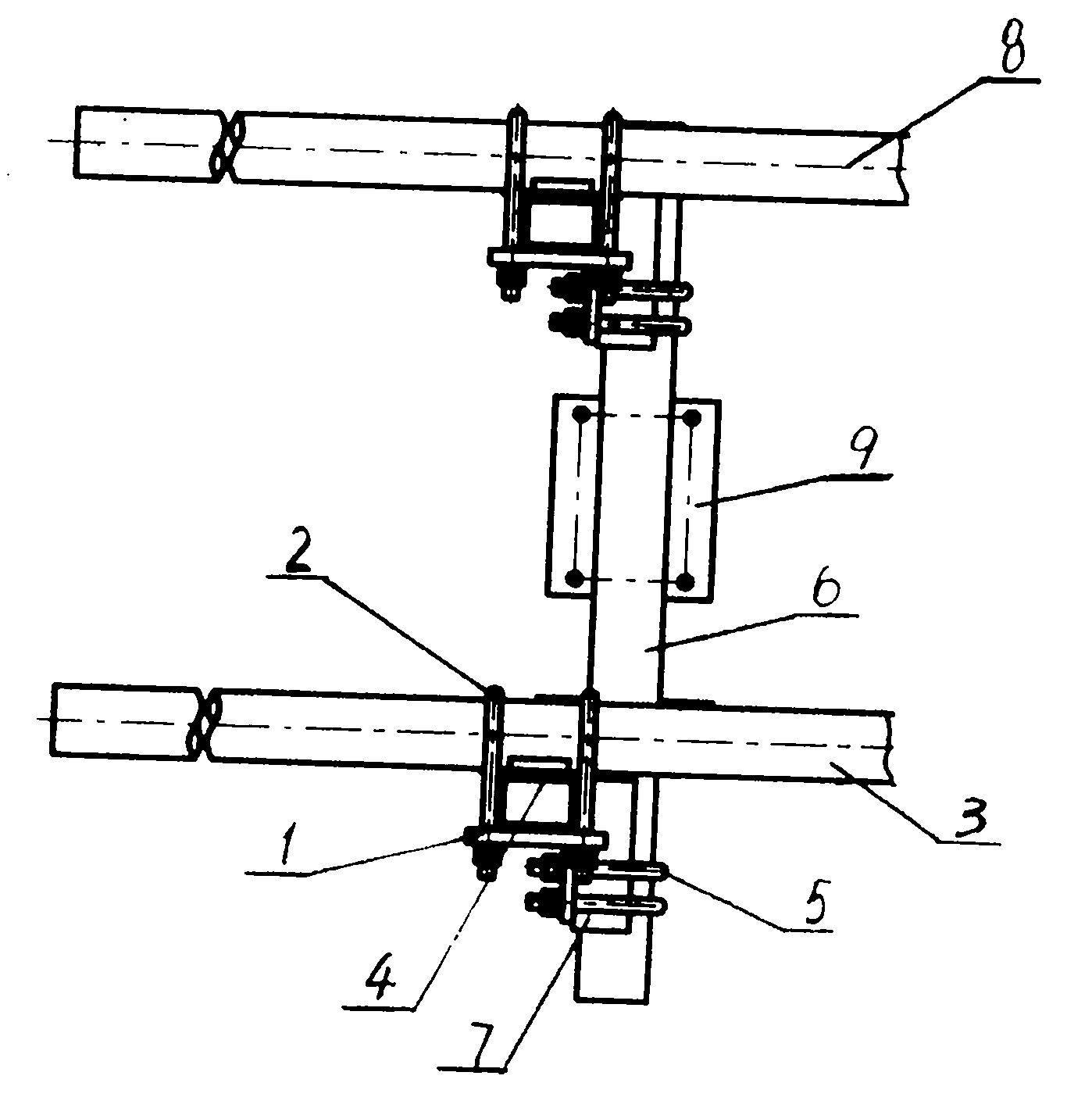
[0010] Embodiments of the present invention will be described in detail below in conjunction with the accompanying drawings. A position adjustment mechanism for the main transmission box of a knapsack corn harvester, the left longitudinal beam 8 and the right longitudinal beam 3 are respectively equipped with a height adjustment beam 4 through the combination of the upper splint 1 and the upper U-shaped card 2, and the lower splint 7 is fixed On the lower part of the height adjustment beam 4, the left and right sides of the lateral position adjustment beam 6 are supported and installed on the left longitudinal beam 8 and the right longitudinal beam 3 through the lower U-shaped card combination 5 and the lower splint 7. On the lower part of the beam 4, on the lateral position adjustment beam 6, the main transmission box mounting seat plate 9 is installed at the position between the left longitudinal beam 8 and the right longitudinal beam 3.

[0011] During installation, install...


PUM


Abstract

The invention relates to a position regulating mechanism of a main transmission box of a backpack corn harvester, belonging to agricultural machinery. High and low level regulating beams are respectively assembled on a left longitudinal beam and a right longitudinal beam through an upper clamp plate and an upper U-shaped card combination, and lower clamp plates are fixedly installed on the lower-side parts of the high and low level regulating beams. The left-side part and the right-side part of a transverse level regulating beam are born on the lower parts of the high and low level regulating beams on the left longitudinal beam and the right longitudinal beam through a lower U-shaped card combination and the lower clamp plates. The part positioned between the left longitudinal beam and the right longitudinal beam on the transverse level regulating beam is provided with a main transmission box installation plate. The position regulating mechanism of the main transmission box of the backpack corn harvester has the advantages of simple structure, simpleness and convenience in regulation, high generalization degree and wide suitable machine types and can cause the backpack corn harvester with one kind of structure to be installed with various types of four-wheel tractors to form ta complete set to use.

Description

technical field [0001] The invention belongs to agricultural machinery, and mainly relates to a position adjustment mechanism of a main transmission box installed in conjunction with a backpack corn harvester and a four-wheel tractor. Background technique [0002] Due to the large number of manufacturers of medium and small power four-wheel tractors in my country, the product models produced are complicated and the structures are different, which makes it inconvenient to install the knapsack corn harvester with the four-wheel tractor, that is, a knapsack corn harvester can only be used with One type of four-wheel tractor is installed as a complete set, and the degree of generalization is greatly reduced, especially the positions of the power output shafts on the rear of various types of four-wheel tractors are different, and the main transmission boxes on the existing backpack corn harvesters of many varieties cannot The adjustment of the position resulted in the failure of th...

Claims


Application Information

Patent Timeline
Patent Type & Authority Applications(China)
IPC IPC(8): A01D67/00A01D69/06A01D45/02
Inventor 王文海戴耀辉
Owner 萝北县新利民农业机械制造有限公司
Why Eureka
Try Eureka