
Non-conductor contact electric power transmission method adopting redundant core protection

A technology for contacting electric energy and transmission methods, applied in transformer/inductor cores, circuits, inductors, etc., can solve problems such as poor handling, over-limit current, and drop in reluctance

Inactive Publication Date: 2012-07-25
姬志刚
View PDF2 Cites 0 Cited by
  • Summary
  • Abstract
  • Description
  • Claims
  • Application Information

AI Technical Summary

Problems solved by technology

[0002] At present, in the field of non-conductor contact power transmission technology, Chinese Patent Publication No. CN102215002A, published on October 12, 2011, and the name of the invention is a non-conductive contact power transmission device, Chinese Patent Publication No. CN202043044U, published on November 2011 On the 16th, the name of the invention was a non-conductor contact power transmission device. The two applications disclosed a device and method for realizing non-conductor contact power transmission. During the replacement, the magnetic circuit at the power supply end changes from closed to open, and the magnetic resistance drops sharply. The current of the original coil at the power supply end runs beyond the limit. Improper handling may cause serious heating, and there is a fire hazard, which seriously affects the safety of electricity use and safe production.

Method used


Image

  • Non-conductor contact electric power transmission method adopting redundant core protection
  • Non-conductor contact electric power transmission method adopting redundant core protection

Examples


Embodiment Construction

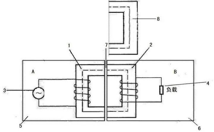
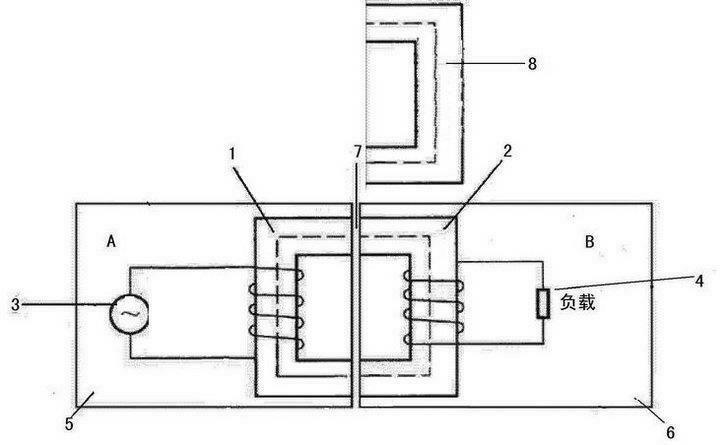
[0007] Such as figure 1 As shown, the non-conductor contact power transmission method using redundant magnetic core protection includes power supply terminal A and power consumption terminal B. Power supply terminal A includes an "E"-shaped power supply terminal iron core 1 and a winding on the power supply terminal iron core 1 The primary coil, the primary coil is connected to the AC power supply 3. The electrical terminal B includes the reverse "E"-shaped electrical terminal iron core 2 and the secondary coil wound on the electrical terminal iron core 2 and the secondary coil connected to both ends of the secondary coil Load 4, after the power supply terminal A and the power terminal B are connected, the power supply side core 1 and the power terminal core 2 form an almost complete "day"-shaped core, and the power supply side core 1 and the power terminal core 2 constitute Closed magnetic field line channel.

[0008] The power supply terminal A also includes the power supply t...


PUM


Abstract

The invention discloses a non-conductor contact electric power transmission method adopting redundant core protection, which comprises a power supply terminal and a power utilization terminal. The power supply terminal comprises an E-shaped power supply terminal core and a primary coil coiled on the power supply terminal core; a redundant core is added; and when a power utilization terminal core is dismounted, the redundant core and the power supply terminal core form a closed magnetic line channel which is connected on an alternating current power supply. The method thoroughly solves the potential safety problem of over heat of the primary coil and is safe and reliable.

Description

Technical field [0001] The invention relates to an electric energy transmission method, more specifically, the invention relates to a non-conductor contact electric energy transmission method using redundant magnetic core protection. Background technique [0002] At present, in the field of non-conductor contact power transmission technology, Chinese Patent Publication No. CN102215002A, published on October 12, 2011, the name of the invention is non-conductor contact power transmission device, Chinese Patent Publication No. CN202043044U, published on November 2011 On the 16th, the invention created the name non-conductor contact electric energy transmission device. The two applications disclose a device and method for realizing non-conductor contact electric energy transmission. The shortcoming is that the design of the power supply end is defective, and the load on the power end When replacing, the magnetic circuit of the power supply end changes from closed to open, the magneti...

Claims


Application Information

Patent Timeline
IPC IPC(8): H02J17/00H01F38/14H01F27/24H02J50/10
Inventor 姬志刚王亚涛杜志刚王俊勇姬志强贾海亮
Owner 姬志刚
Learn More