Magnetic suspension molecular pump rotor floating position selection method and rotor floating control method

A magnetic levitation and molecular pump technology, applied in pump control, non-variable pumps, machines/engines, etc., to achieve stable working characteristics and stable floating effects

Active Publication Date: 2012-07-25
KYKY TECH +1
View PDF6 Cites 9 Cited by
  • Summary
  • Abstract
  • Description
  • Claims
  • Application Information

AI Technical Summary

Problems solved by technology

However, the method for selecting the floating position of the rotor of the magnetic levitation molecular pump in advance has not been disclosed in the prior art.

Method used


Image

  • Magnetic suspension molecular pump rotor floating position selection method and rotor floating control method
  • Magnetic suspension molecular pump rotor floating position selection method and rotor floating control method
  • Magnetic suspension molecular pump rotor floating position selection method and rotor floating control method

Examples


Embodiment 1

[0041] This embodiment provides a method for selecting the floating position of the rotor of a magnetic levitation molecular pump, which includes the following steps:

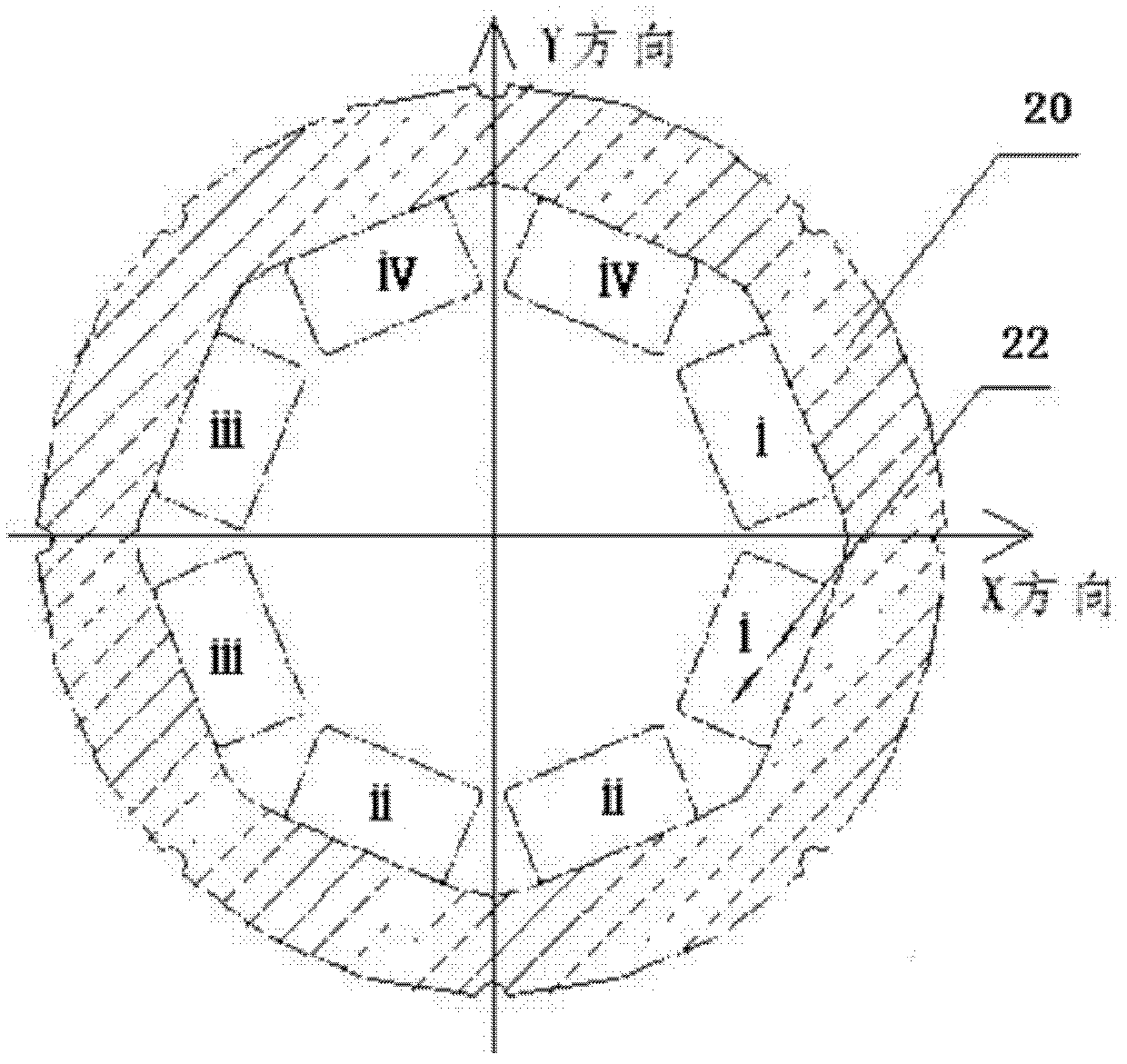
[0042] I. Establish a Cartesian coordinate system with the center of the inner circle of the radial protective bearing stator as the origin, and divide the inner circle of the radial protective bearing stator into n sectoral intervals on average (n is a natural number and n≥4);

[0043] II. Obtaining the float control parameters of the rotor and the float characteristic parameters of the rotor when the rotors are respectively located in the n intervals through a levitation test;

[0044] III. Comparing the floating characteristic parameters when the rotors are respectively located in the n intervals, selecting the optimal interval suitable for the floating of the rotor, and outputting the X direction output of the corresponding radial displacement sensor when the rotor is located in the optimal interval The sig...

Embodiment 2

[0057] In this embodiment, on the basis of Embodiment 1, further, the step II further includes acquiring the float control parameters of the rotor and the float control parameters of the rotor when the rotor is located at multiple positions in the preferred interval. The steps of floating characteristic parameters;

[0058] The step III also includes comparing the float control parameters of the rotor and the float characteristic parameters of the rotor when the rotor is located in multiple positions in the preferred interval, and obtaining the float characteristics of the rotor in the optimal interval The best preferred position, when the rotor is at the preferred position, the corresponding X-direction output signal voltage amplitude, Y-direction output signal voltage amplitude and rotor float control parameters of the corresponding radial displacement sensor are stored in the controller 2 steps in the storage medium within.

[0059] Correspondingly, in the rotor float cont...


PUM


Abstract

The invention discloses a magnetic suspension molecular pump rotor floating position selection method and a rotor floating control method. The inner circle center of a radial protection bearing stator serves as an original point to establish a rectangular coordinate system, the inner circle of the radial protection bearing stator is averagely divided into n sectorial intervals, and floating control parameters and floating characteristic parameters of rotors are obtained when the rotors are positioned in the intervals by means of suspension test. One interval or two intervals with the best floating characteristic is selected from the n intervals to serve as rotor floating preferential intervals, and the voltage amplitude ranges of X-directional output signals and Y-directional output signals of radial displacement sensors corresponding to the preferential intervals and the floating control parameters are recorded in a storage medium of a controller. When a magnetic suspension molecular pump starts working, the controller of the magnetic suspension molecular pump controls a motor to drive the rotors to reach the preferential intervals and then calls the floating control parameters stored in the controller to control the rotors to float, so that the rotors can rapidly and stably float.

Description

technical field [0001] The invention relates to the technical field of vacuum obtaining equipment application, in particular to a method for selecting a floating position of a rotor of a magnetic levitation molecular pump and a method for controlling the floating of the rotor. Background technique [0002] The magnetic suspension molecular pump is a molecular pump that uses magnetic bearings as the rotor support. It uses magnetic bearings to suspend the rotor stably in the air, so that there is no mechanical contact between the rotor and the stator during high-speed operation, and it has no mechanical wear and energy consumption. Low speed, high allowable speed, low noise, long life, no need for lubrication, etc. At present, the magnetic levitation molecular pump is widely used in the fields of obtaining high vacuum and high cleanliness vacuum environment. [0003] The internal structure of the magnetic levitation molecular pump is as follows: figure 1 As shown, the magneti...

Claims


Application Information

Patent Timeline
Patent Type & Authority Applications(China)
IPC IPC(8): F04D27/00
Inventor 张剀武涵李奇志张小章邹蒙
Owner KYKY TECH
Why Eureka
Try Eureka