
Saucer-shaped aircraft

A saucer-shaped aircraft and guide vane technology, applied in the field of aircraft, can solve problems such as increased energy consumption, difficulty in speed adjustment, waste of resources, etc., and achieve the effects of reduced air resistance, novel structural design, and stable hovering in the air

Inactive Publication Date: 2012-07-18
BEIJING UNIV OF TECH
View PDF6 Cites 16 Cited by
  • Summary
  • Abstract
  • Description
  • Claims
  • Application Information

AI Technical Summary

Problems solved by technology

However, due to the existence of the gyro effect and the complex aerodynamic characteristics of the ducted fan, during the forward flight, the aircraft tends to maintain its horizontal state and struggle to adjust its attitude. In the flow field, it is very easy to cause the airflow around the fuselage to be turbulent, the flight state of the aircraft is unstable, the speed adjustment is difficult, and there is even the danger of the aircraft losing control
In addition, problems such as instability during flight and tilting of the fuselage also lead to the inability of the airborne equipment to work normally and effectively.
At the same time, tilting the fuselage also causes lift loss and increases energy consumption
[0003] In terms of aircraft hovering in the air, the existing aircraft powered by propellers or rotors are exposed to the outside and are easily disturbed by airflow, resulting in poor stability and difficult control
At the same time, this type of aircraft can only rely on the lift provided by its propeller or rotor to maintain its hovering, and cannot use other parts of the fuselage to generate lift, resulting in waste of resources

Method used


Image

  • Saucer-shaped aircraft
  • Saucer-shaped aircraft
  • Saucer-shaped aircraft

Examples


Embodiment Construction

[0030] Embodiments of the present invention are further described in detail in conjunction with the accompanying drawings

[0031] Working principle of the present invention:

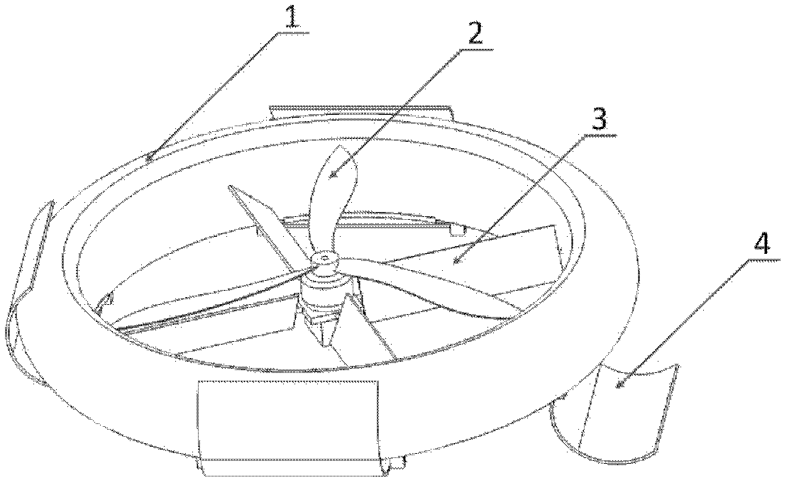
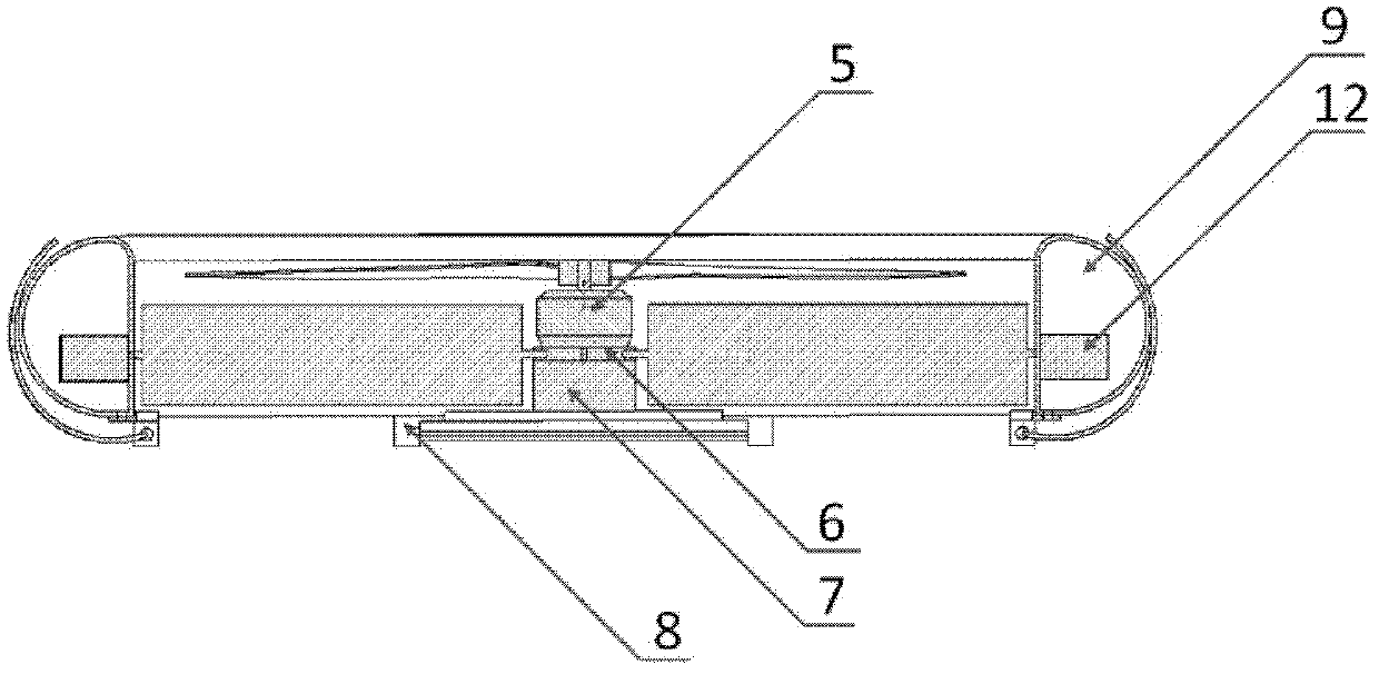
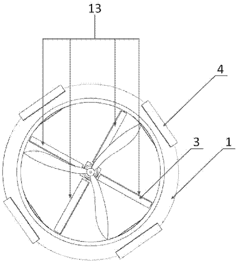
[0032] A saucer-shaped aircraft, comprising: a brushless DC motor 5, a propeller 2, a steering gear 12, a battery 7, a guide vane group 13 including a guide vane 3, and a duct body 1; the propeller 2 is fixed on the brushless DC motor 5 superior,

[0033] It is characterized in that it also includes a fixed block 6, the brushless DC motor 5 is connected to the upper surface of the fixed block 6, one end of the guide vane 3 is connected to the fixed block 6, and the other end is connected to the inner surface of the duct body 1, and the lower surface of the fixed block 6 is fixed There is a battery 7; it also includes a direction control rudder 4 and a control rudder connecting frame 8;

[0034] The direction control rudder 4 is formed by bending a rectangular plate into an arc along the direction of t...


PUM


Abstract

The invention discloses a saucer-shaped aircraft, which belongs to the field of aviation. The saucer-shaped aircraft comprises a brushless direct current motor (5), a screw propeller (2), a steering engine (12), a battery (7), a guide vane set (13) comprising guide vanes (3) and a culvert body (1), wherein the screw propeller (2) is fixed to the brushless direct current motor (5). The saucer-shaped aircraft is characterized by also comprising a fixing block (6), a direction control rudder (4) and a control rudder connecting frame (8), wherein the brushless direct current motor (5) is connected with the upper surface of the fixing block (6); one end of each of the guide vanes (3) is connected with the fixing block (6), and the other end of each of the guide vanes (3) is connected with the inner surface of the culvert body (1); the battery (7) is fixed on the lower surface of the fixing block (6); the direction control rudder (4) is formed by bending a rectangular plate in the directions of two parallel edges of the rectangular plate; and the control rudder connecting frame (8) is fixed to the culvert body for supporting the direction control rudder. The saucer-shaped aircraft has the advantages of stable flying, easiness for operation and control, stable hovering and superior performance in tasks such as air photography and air detection.

Description

technical field [0001] The invention designs an aircraft, in particular relates to a dish-shaped aircraft, and belongs to the technical field of aviation. Background technique [0002] At present, most dish-shaped aircraft use ducted fans, rotors or propellers as their power sources. During their forward flight, in order to obtain forward horizontal thrust, the attitude of the aircraft must be adjusted, that is, the fuselage must be tilted. However, due to the existence of the gyro effect and the complex aerodynamic characteristics of the ducted fan, during the forward flight, the aircraft tends to maintain its horizontal state and struggle to adjust its attitude. In the flow field, it is very easy to cause the airflow around the fuselage to be turbulent, the flight state of the aircraft is unstable, the speed adjustment is difficult, and there is even the risk of the aircraft losing control. In addition, problems such as instability during flight and tilting of the fuselag...

Claims


Application Information

Patent Timeline
IPC IPC(8): B64C39/06
Inventor 阮晓钢赵秉辉侯旭阳朱晓庆李亚磊高静欣
Owner BEIJING UNIV OF TECH
Learn More