Mounting structure of component in large-sized container

A technology for the installation of large-scale containers and components, applied in auxiliary devices, auxiliary welding equipment, welding/cutting auxiliary equipment, etc. Limits and other issues, to achieve the effect of easy non-destructive testing, greater freedom of work, and improved dimensional accuracy of assembly

Active Publication Date: 2014-12-03
SHANGHAI ELECTRIC POWER GENERATION EQUIPMENT CO LTD
View PDF9 Cites 0 Cited by
  • Summary
  • Abstract
  • Description
  • Claims
  • Application Information

AI Technical Summary

Problems solved by technology

If a single internal component is assembled and welded into the shell separately, the workload is huge, the labor intensity of the workers is high, the manufacturing cycle is long, the work efficiency is low, and the welding position is limited, the non-destructive testing operation is limited, and the assembly size of the internal components Low precision, it is difficult to meet the requirements of drawing size and manufacturing progress

Method used


Image

  • Mounting structure of component in large-sized container
  • Mounting structure of component in large-sized container
  • Mounting structure of component in large-sized container

Examples


Embodiment Construction

[0018] see Figure 1 to Figure 4 , in order to better understand the technical solution of the present invention, the following will be described in detail through specific embodiments and in conjunction with the accompanying drawings:

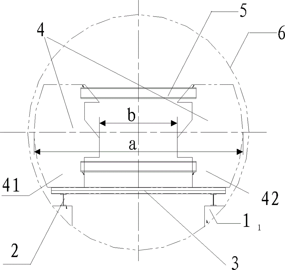
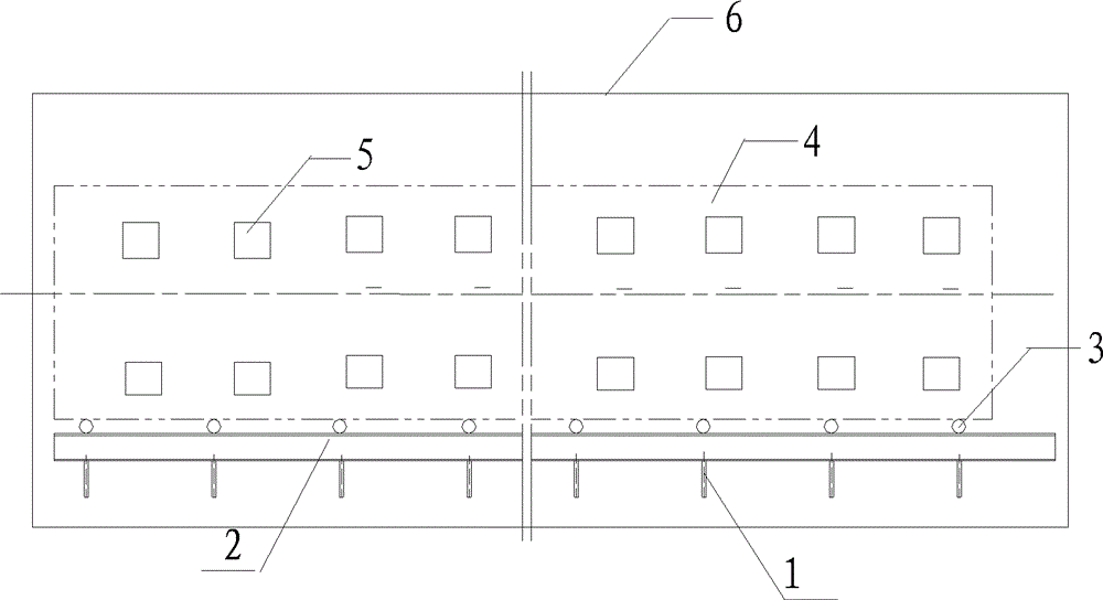
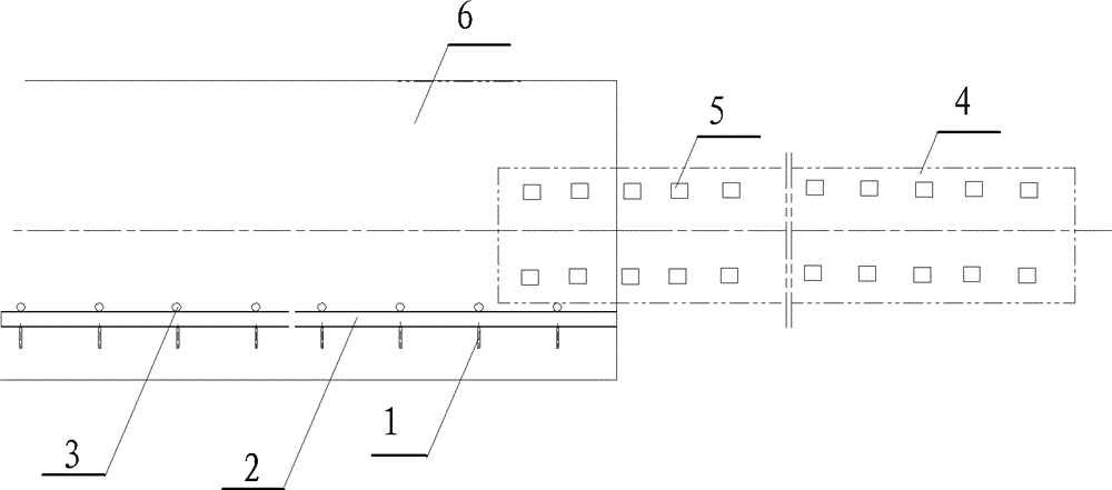
[0019] see figure 1 , a large container internal components installation structure of the present invention, including support plate 1, I-beam 2, process steel pipe 3, internal integral components 4 and process channel steel 5. Wherein the support plate 1 and the I-beam 2 constitute a mounting bracket, and the axial direction of the mounting bracket is parallel to the axial direction of the large container.

[0020] The support plates 1 are symmetrically arranged in two rows along the axial direction of the large container 6 on the bottom surface of the inner wall on both radial sides of the large container, and the I-beams 2 are erected symmetrically in two rows along the sides of the large container 6. On the top surfaces of the support pl...


PUM


Abstract

The invention discloses a mounting structure of a component in a large-sized container. The mounting structure comprises a mounting bracket, technical steel pipes, the inner integral component and technical steel channels. The mounting bracket is mounted on the bottom surface of the inner wall of the large-sized container, the top of the mounting bracket keeps horizontal, the axial direction of the mounting bracket is parallel to that of the large-sized container, the technical steel pipes are disposed on the top of the mounting bracket, are sequentially arrayed along the axial direction of the mounting bracket and can roll along the axial direction of the mounting bracket, the outer diameter alpha of the inner integral component is smaller than the inner diameter of the large-sized container, the inner integral component consists of a left inner integral component and a right inner integral component, the left inner integral component and the right inner integral component are connected by the technical steel channels to form the inner integral component, and the technical steel channels are sequentially arrayed along the axial direction of the inner integral component.

Description

technical field [0001] The invention relates to an installation structure of internal components of a large container. Background technique [0002] Mist-water separation reheater (MSR) is a key equipment dedicated to nuclear power steam turbines. The main steam from the nuclear island steam generator expands step by step in the high-pressure cylinder to work, and the pressure and temperature of the steam decrease step by step, leaving the final blade of the high-pressure cylinder The humidity of the exhaust steam is as high as 10% to 14%. Such steam is introduced into the low-pressure cylinder to continue to expand and do work. When it reaches the pressure of the condenser, the humidity of the exhaust steam will increase to 20% to 25%, far exceeding 12% to 15%. The allowable value, in addition to greatly reducing the efficiency of the steam turbine, will also cause serious water erosion of the internal components of the steam turbine, so that the unit cannot work normally. ...

Claims


Application Information

Patent Timeline
Patent Type & Authority Patents(China)
IPC IPC(8): B23K37/00B23P19/00
Inventor 朱坚谢华韩石明
Owner SHANGHAI ELECTRIC POWER GENERATION EQUIPMENT CO LTD
Why Eureka
Try Eureka