Devices in a printing couple of a printing machine

A technology for printing devices and printing machines, which is applied to printing machines, general parts of printing machinery, rotary printing machines, etc., can solve problems such as shaft couplings that have not been elaborated, achieve belt replacement and maintenance simplification, save materials, and simplify construction Effect

Inactive Publication Date: 2014-08-13
KOENIG & BAUER AG
View PDF19 Cites 0 Cited by
  • Summary
  • Abstract
  • Description
  • Claims
  • Application Information

AI Technical Summary

Problems solved by technology

Balance for reciprocating lift in the coupling is not elaborated

Method used


Image

  • Devices in a printing couple of a printing machine
  • Devices in a printing couple of a printing machine
  • Devices in a printing couple of a printing machine

Examples


Embodiment Construction

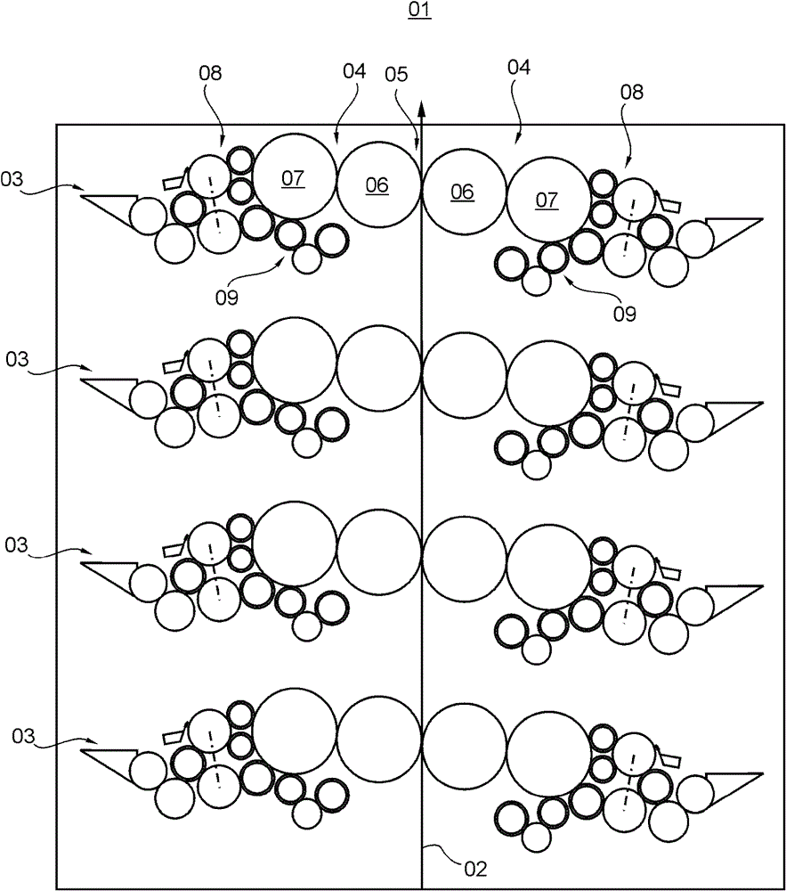
[0038] A printing press, such as a web rotary printing press, in particular a multicolor web rotary printing press, has at least one printing unit 01 in which double-sided single (einfach) or in particular sequential (mehrfach) multiple (mehrfach) ), such as quadruple printing a material belt 02, referred to as belt 02, or printing multiple belts 02 in single or multiple times at the same time.

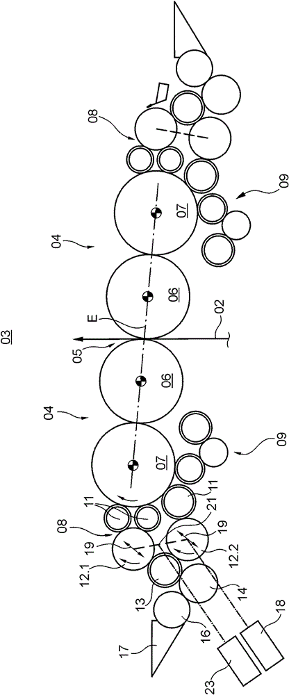
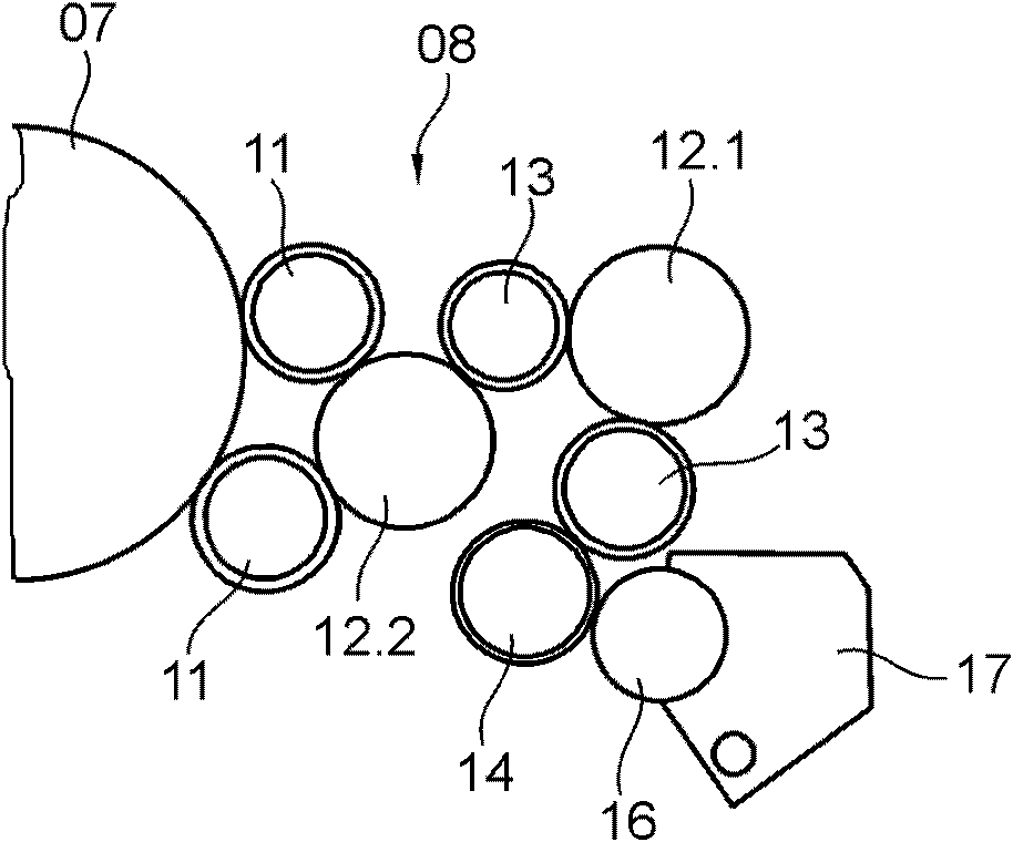
[0039] exist figure 1The printing unit 01 shown in is designed in the form of a printing tower with a substantially vertical rail run and has a plurality, in the present case 4, of double printing units 03 arranged vertically one above the other for printing on the rubber- Double-sided printing in rubber production (Gummi-Gegen-Gummi-Betrieb). Such a printing unit 01 designed in the form of a printing tower with a track running through the printing unit 01 from bottom to top is preferably arranged in a newspaper printing machine, wherein the newspaper printing machine has, for exampl...


PUM


Abstract

The invention relates to devices in a printing couple (04) of a printing machine, at least comprising at least one roll (12; 12.1; 12.2; 12.3), which is mounted axially movably on both sides in side frames (30), of an inking system (08) or damping system (09) of the printing couple (04), to which roll a temperature control agent can be fed on an end face via an interface (24) for controlling the temperature of the roll, wherein at least one transversing drive (22) for generating an axial transversing stroke of the roll (12; 12.1; 12.2; 12.3) and at least one drive means (18) for generating a rotatory movement of the roll (12; 12.1; 12.2; 12.3) are provided. The rotatory drive means (18) and the transversing drive (22) engage with same end face of the roll (12; 12.1; 12.2; 12.3) opposite of the interface (24). Between the roll (12; 12.1; 12.2; 12.3) and the rotatory drive means (18), a coupling (27) comprising two rotors (41, 42) that can be moved axially relative to each other are provided, for compensating for the transversing stroke caused by the transversing drive (22). A first of the rotors (41, 42) is mounted rotatably in or on the side frame (30), however mounted in a stationary manner with respect to an axial direction and is mechanically coupled to the drive means (18) for the rotatory drive thereof. The second of the rotors (41, 42) is connected to a journal (28) of the roll (12; 12.1; 12.2; 12.3) in a non-rotational, tension-resistant and compression-resistant manner.

Description

technical field [0001] The invention relates to a device in a printing unit of a printing press. Background technique [0002] WO 03 / 039873 A1 discloses an inking unit with two friction cylinders which, in one embodiment, are co-rotatable on the same machine side by a drive motor via a belt drive and by a further drive motor via a belt drive. The crank gear is driven in reciprocating movement. The belt is driven on pulleys, which carry out a lifting movement via a correspondingly widened running surface or via a movement guided on a pin. [0003] WO 2005 / 097505 A2 discloses a printing unit with an inking unit, in which two friction cylinders are jointly driven in rotation and reciprocatingly via a transmission arranged in the housing. [0004] DE 10 2007 000 554 A1 discloses a drive concept for two friction rollers, wherein only one of the two friction rollers is forced to rotate in operation via a pinion by a drive motor, and the two friction rollers are driven by the dri...

Claims


Application Information

Patent Timeline
Patent Type & Authority Patents(China)
IPC IPC(8): B41F13/008B41F31/00B41F31/15
CPCB41F31/004B41F13/008B41F31/15B41P2213/25
Inventor 埃里希·马科斯·卡尔·格尔纳瑞加娜·丽塔·舍勒本杰明·齐罗尔德
Owner KOENIG & BAUER AG
Why Eureka
Try Eureka