
Optical transmitting antenna system and beam control method thereof

A technology of optical transmitting antenna and optical antenna, which is applied in the field of laser communication, can solve complex problems, and the impact on motion will be more significant

Inactive Publication Date: 2012-07-11
XIDIAN UNIV
View PDF4 Cites 15 Cited by
  • Summary
  • Abstract
  • Description
  • Claims
  • Application Information

AI Technical Summary

Problems solved by technology

At present, the research on APT technology focuses on traditional mechanical methods such as stepping motors or fast vibrating mirrors. In fixed-point FSO communication, the automatic adjustment mechanical device of the system itself overcomes the influence of small-scale device vibration and deformation. Meet the requirements of laser communication accuracy; in space FSO communication (such as between satellites and satellites and between satellites and the ground), through precise control of stable platforms and high-speed galvanometers, laser communication accuracy requirements can also be met, but its The price is the need to design a complex APT system; and for near-earth mobile (especially fast-moving) atmospheric laser communication systems, due to the influence of atmospheric effects and relative motion of the target will be more significant, the current APT technology cannot meet the requirements of laser communication

Method used


Image

  • Optical transmitting antenna system and beam control method thereof
  • Optical transmitting antenna system and beam control method thereof
  • Optical transmitting antenna system and beam control method thereof

Examples


Embodiment Construction

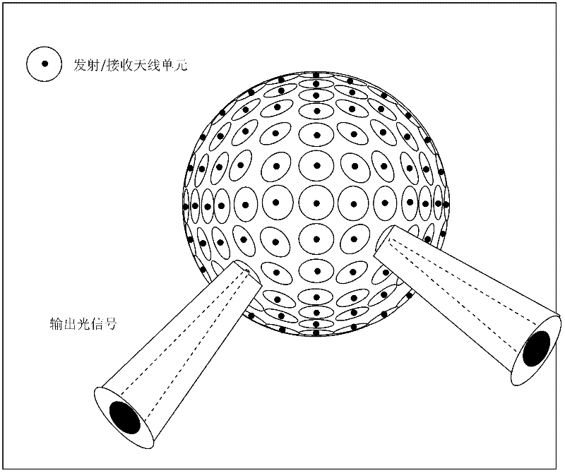
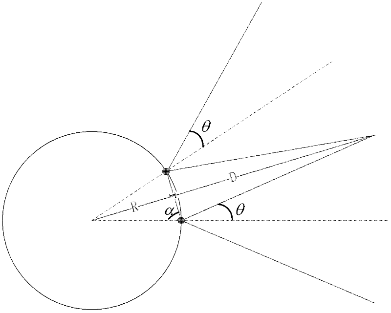
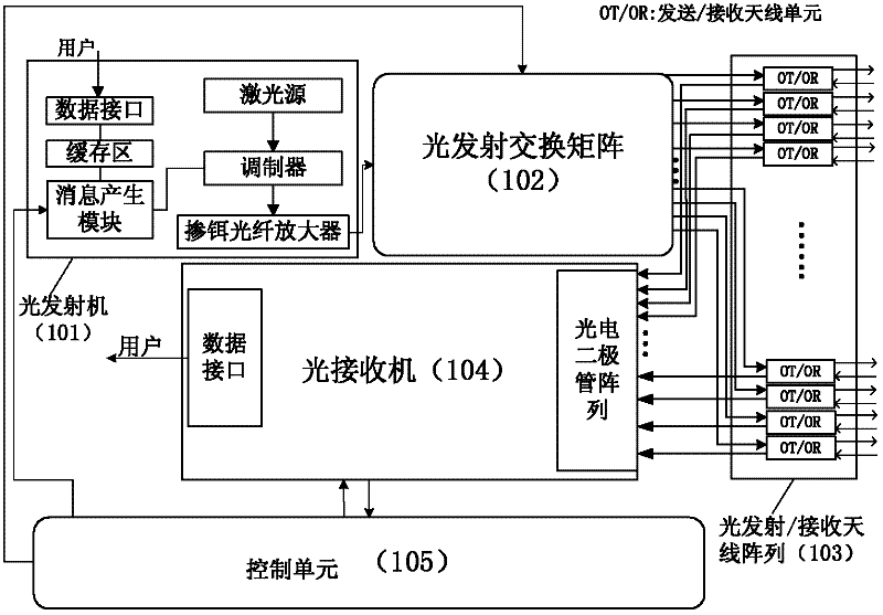
[0111] see figure 1 , the optical antenna proposed by the present invention is exactly a kind of array structure of n laser transmitting and receiving antennas uniformly arranged on an arc surface (covering solid angle is Ω) by using angle classification technology, and the transmitting antennas in the array are stimulated by laser emission Switching matrix control, each receiving antenna is photoelectrically converted by the photodiode in the receiver and detects the optical power, and the input / output path of the laser is switched according to the control algorithm, so as to achieve flexible control of the number and direction of the transmitted beam and flexible setting. For the purpose of the position of the antenna unit receiving the optical signal, realize the intelligent capture, alignment and tracking process between the two antenna systems, and finally realize the optical communication between moving objects, especially between high-speed moving objects.

[0112] The ...


PUM


Abstract

The invention discloses an optical transmitting antenna system and a beam control method thereof. An optical antenna has an array structure which is formed by uniformly arranging a plurality of laser transmitting antennae and a plurality of receiving antennae. The array structure is arranged on a cambered surface (a hemispherical surface or a spherical surface). Each laser transmitting antenna comprises a transmitting multimode fiber and a transmitting micro-lens. Each receiving antenna comprises a receiving multimode fiber and a receiving micro-lens. A transmitting micro-lens is positioned in the center of each receiving micro-lens. By the optical transmitting antenna system and the beam control method thereof, the mobile communication of a near-earth atmospheric laser system is well realized, dependence on a complex acquisition pointing and tracking (APT) system is reduced, and communication reliability is improved.

Description

technical field [0001] The invention belongs to the technical field of laser communication, and in particular relates to a multi-beam optical antenna device based on beam controllable technology in a mobile atmospheric laser communication system, which utilizes the line-of-sight transmission characteristics of beams, angle diversity technology and control algorithms to realize intelligent communication between optical antennas. capture, alignment and tracking. Background technique [0002] Atmospheric laser communication, also known as Free Space Optical Communication (FSO) or Wireless Optical Communication (Wireless Optical Communication), is an emerging wireless communication method that can carry both digital and radio frequency signals. It has the advantages of large communication capacity, good security and confidentiality, strong anti-electromagnetic interference ability, and no need to apply for wireless frequency bands. It has important application value in the field...

Claims


Application Information

Patent Timeline
IPC IPC(8): H04B10/10H04B10/02G02B6/42
Inventor 岳鹏王拓黎倩男顾华玺易湘鞠茂光刘增基王宇
Owner XIDIAN UNIV
Learn More