
End hydraulic bracket with rotatable top beam

A technology of end hydraulic support and roof beam, which is applied to mine roof support, mining equipment, earth-moving drilling, etc., can solve the loss of stability of the support and the ability to support the inclined roof, and restrict the development of rapid and efficient production of comprehensive mining. , It can not solve the problems of support and forward movement of the sloped roof roadway, and achieves the effect of good stability of the support, easy disassembly and assembly, and novel form.

Inactive Publication Date: 2012-07-11
CHONGQING DAJIANG IND
View PDF5 Cites 1 Cited by
  • Summary
  • Abstract
  • Description
  • Claims
  • Application Information

AI Technical Summary

Problems solved by technology

The support of flat-roof roadway is relatively easy to solve, but the support of inclined-roof roadway is much more difficult. Generally, the support used for flat-roof roadway cannot solve the problem of stability support of inclined-roof roadway
The main reason is that the upward and sideward component force generated by the support top beam supporting the inclined roof will cause the top beam to slide upward and sideways, making the support lose its stability and the ability to support the inclined roof; in addition, it cannot solve the problem of slope roof roadway The problem of supporting and moving forward greatly affects and restricts the development of rapid and efficient production in comprehensive mining

Method used


Image

  • End hydraulic bracket with rotatable top beam
  • End hydraulic bracket with rotatable top beam
  • End hydraulic bracket with rotatable top beam

Examples


Embodiment Construction

[0067] The specific implementation manners of the present invention will be described in detail below in conjunction with the accompanying drawings.

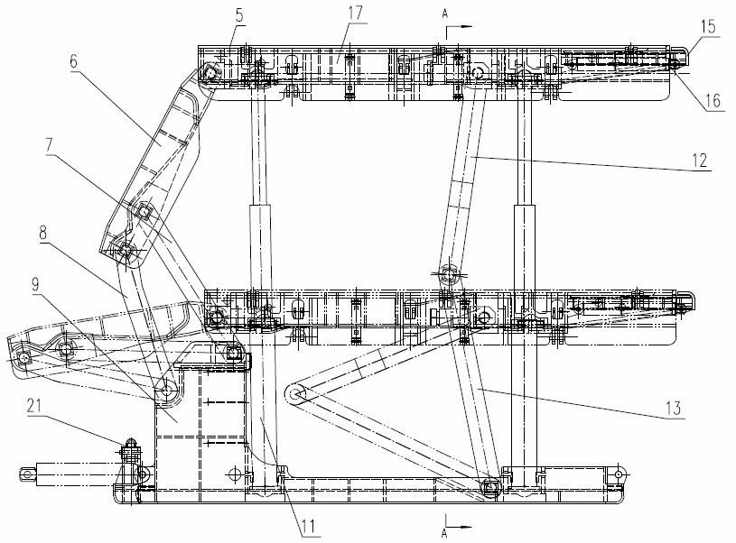
[0068] see figure 1 with figure 2 The shown hydraulic support at the end of a top beam that can be rotated includes a front frame 1, a middle frame 2 and a rear frame 3, and two moving pieces are arranged at the front end of the second base 23 of the middle frame 2. Jack 4, one end of two moving jacks is connected on the middle frame, and the other end is close to the rear end of the first base 9 of the front frame 1; the front end of the third base 27 of the rear frame 3 is also provided with two moving jacks 4. One end of the two moving jacks is connected to the rear frame, and the other end is close to the rear end of the second base 23 of the middle frame 2; at the front of the first base 9 of the front frame 1, the second base of the middle frame 2 23 fronts and the third base 27 fronts of the rear frame 3 are respective...


PUM


Abstract

The invention discloses an end hydraulic bracket with a rotatable top beam, comprising a pair of middle frames, a pair of rear frames and at least one pair of front frames. Two pushing jacks are arranged at the front ends of second bases of the middle frames, one end of each of the pushing jacks is connected on the middle frames, and the other end of each of the pushing jacks adjoins the rear end of the first base; two pushing jacks are arranged at the front ends of third bases of the rear frames, one end of each of the two pushing jacks is connected on the rear frames, and the other end of each of the pushing jacks adjoins the rear ends of the second bases of the middle frames; two bottom lifting jacks are arranged on one of the front part of the first base of the front frame, the front part of the second base of the middle frame and the front part of the third base of the rear frame; and elevating conveyors are arranged on the first bases, the second bases and the third bases, front conveyer heads are arranged on the second bases of the middle frames, and rear conveyer heads are arranged on the third bases of the rear frames. The end hydraulic bracket with the rotatable top beam is suitable for the changes of lane height, dip angle direction and an angle, ensures the stability of the bracket, and realizes the smooth movement when being fixed at the bottom.

Description

technical field [0001] The invention relates to a support facility for coal mines, in particular to a hydraulic support at the end of which the roof beam can be rotated, and is especially suitable for roadways where the inclined roof frequently changes the direction of inclination. Background technique [0002] With the development of mechanized coal mining in coal mines, especially comprehensive mining, the problem of fast and safe support for the roadway (including machine roadway and wind roadway) of the mining face has emerged. The support of flat-roofed roadways is relatively easy to solve, but the support of inclined-roofed roadways is much more difficult. Generally, the supports used for flat-roofed roadways cannot solve the problem of stable support for inclined-roofed roadways. The main reason is that the upward and sideward component force generated by the support top beam supporting the inclined roof will cause the top beam to slide upward and sideways, making the...

Claims


Application Information

Patent Timeline
IPC IPC(8): E21D23/06E21D23/16E21D23/22
Inventor 张治华何光强姜林周谦史亚军麦筱蕙李茂华孙占林李顺秋安蜀文贾华宪袁晓非
Owner CHONGQING DAJIANG IND
Learn More