Push switch and method of manufacturing the same
A button and switch technology, applied in electrical switches, electrical components, circuits, etc., can solve the problems of reducing the risk of water resistance of button switches, reducing productivity, gaps between resin and switch housing, etc., so as to shorten the installation time, The effect of increasing productivity
- Summary
- Abstract
- Description
- Claims
- Application Information
AI Technical Summary
Problems solved by technology
Method used
Image
Examples
no. 1 Embodiment approach
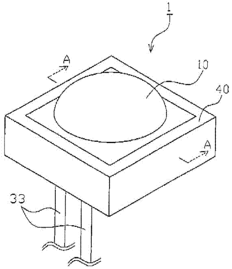
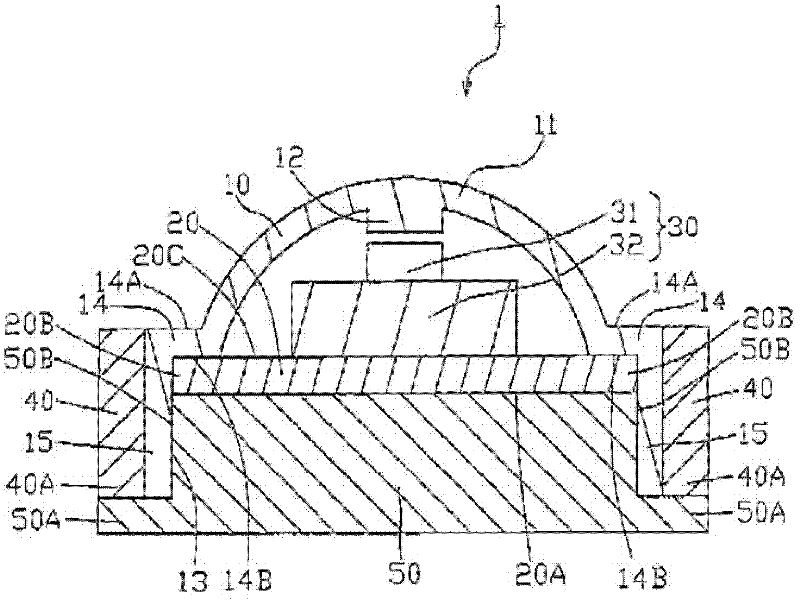
[0097] figure 1 It is a completed perspective view of the push button switch 1 according to the first embodiment of the present invention. figure 2 of the first embodiment of the present invention figure 1 Sectional view of section line A-A. The button switch 1 of this embodiment is as figure 2 As shown, there are button 10 , switch board 20 , switch 30 , outer wall 40 , and lower wall 50 .
[0098] The push button switch 1 of the present embodiment is mounted on an opening hole of a door handle device for a vehicle (not shown). The push button 10 of the push button switch 1 is mounted on the opening hole of the door handle device so as to be exposed to the outside. When the button 10 is pressed by a vehicle user's finger or the like, the door can be locked or unlocked.
[0099] Button 10 is a part that covers switch 30, such as figure 2 It is integrally molded from soft resin as shown. The button 10 has a cap-shaped upper operating portion 11 protruding outward fr...
no. 2 Embodiment approach
[0125] Figure 5 It is a cross-sectional view of a push button switch according to a second embodiment of the present invention.
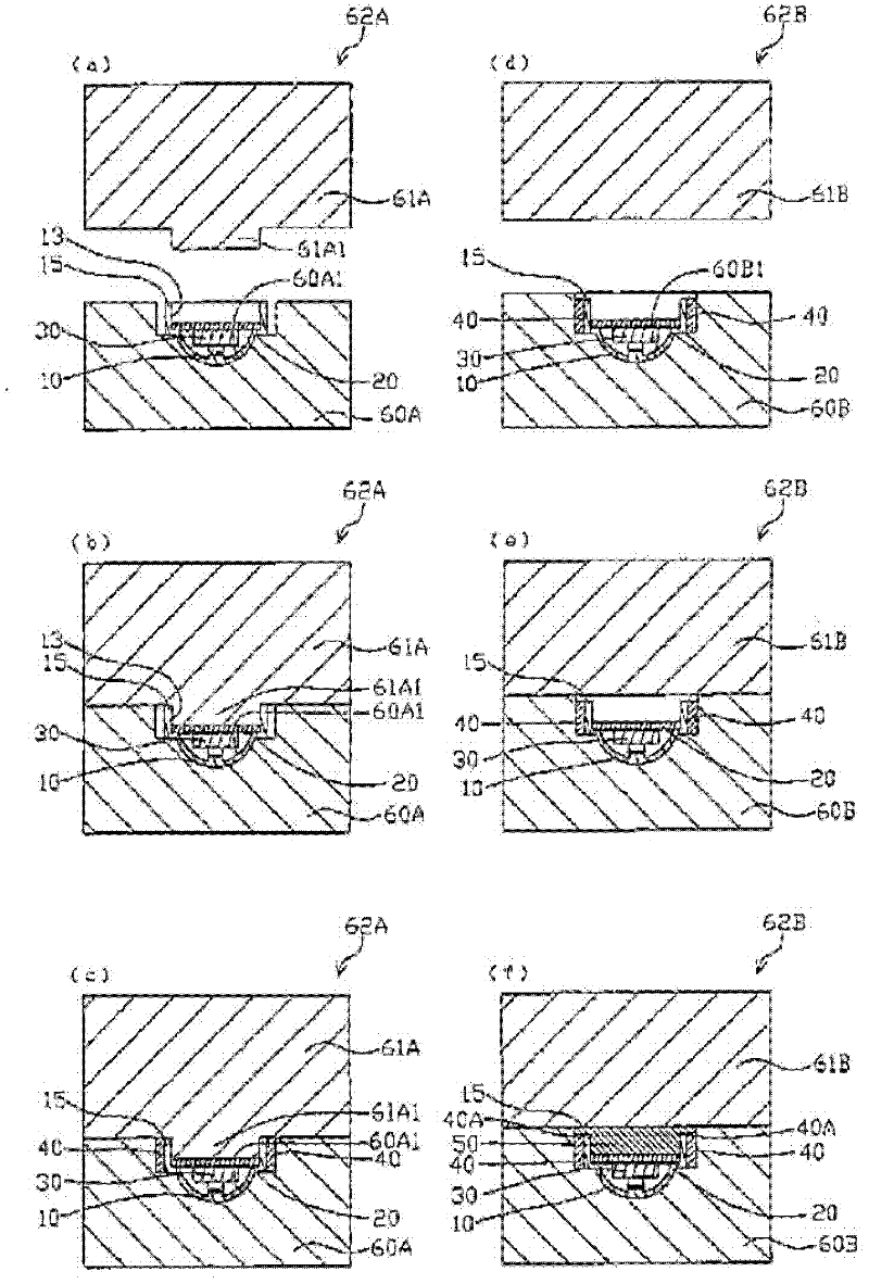
[0126] Image 6 (a) is a cross-sectional view of a state in which a button including a switch substrate is inserted into a primary molding die according to the second embodiment of the present invention. Image 6 (b) is a cross-sectional view of the state in which the primary molding die of the second embodiment of the present invention is closed. Image 6 (c) is a cross-sectional view of a state in which resin is injected into the primary molding die according to the second embodiment of the present invention. Image 6 (d) will be the second embodiment of the present invention Image 6 (c) is a cross-sectional view of the button inserted into the secondary molding die. Image 6 (e) is a sectional view of the state in which the secondary molding die of the second embodiment of the present invention is closed. Image 6 (f) is a cross-sectional ...
no. 3 Embodiment approach
[0143] Figure 7 It is a cross-sectional view of a push button switch according to a third embodiment of the present invention.
[0144] Figure 8 (a) is a cross-sectional view of a state in which a button having a switch substrate is inserted into a molding die according to a third embodiment of the present invention. Figure 8 (b) is a cross-sectional view of a state in which a molding die is closed according to a third embodiment of the present invention. Figure 8 (c) is a cross-sectional view of a state in which a resin is injected into a molding die according to a third embodiment of the present invention. right Figure 7 , Figure 8 Components that are the same as those in the first embodiment are denoted by the same symbols, and overlapping descriptions are omitted.
[0145]Differences between this embodiment and the first embodiment will be described. In the first embodiment, the button 10 on which the switch substrate 20 is arranged is inserted into the primary...
PUM
 Abstract
Description
Claims
Application Information
 - R&D
- Intellectual Property
- Life Sciences
- Materials
- Tech Scout
- Unparalleled Data Quality
- Higher Quality Content
- 60% Fewer Hallucinations
Browse by: Latest US Patents, China's latest patents, Technical Efficacy Thesaurus, Application Domain, Technology Topic, Popular Technical Reports.
© 2025 PatSnap. All rights reserved.Legal|Privacy policy|Modern Slavery Act Transparency Statement|Sitemap|About US| Contact US: help@patsnap.com


