Shutter type display screen
A display screen and louver technology, applied in the field of display screen, can solve the problem that the LED louver screen cannot meet the requirements of the louver, and achieve the effect of improving the utilization rate
- Summary
- Abstract
- Description
- Claims
- Application Information
AI Technical Summary
Problems solved by technology
Method used
Image
Examples
no. 1 example
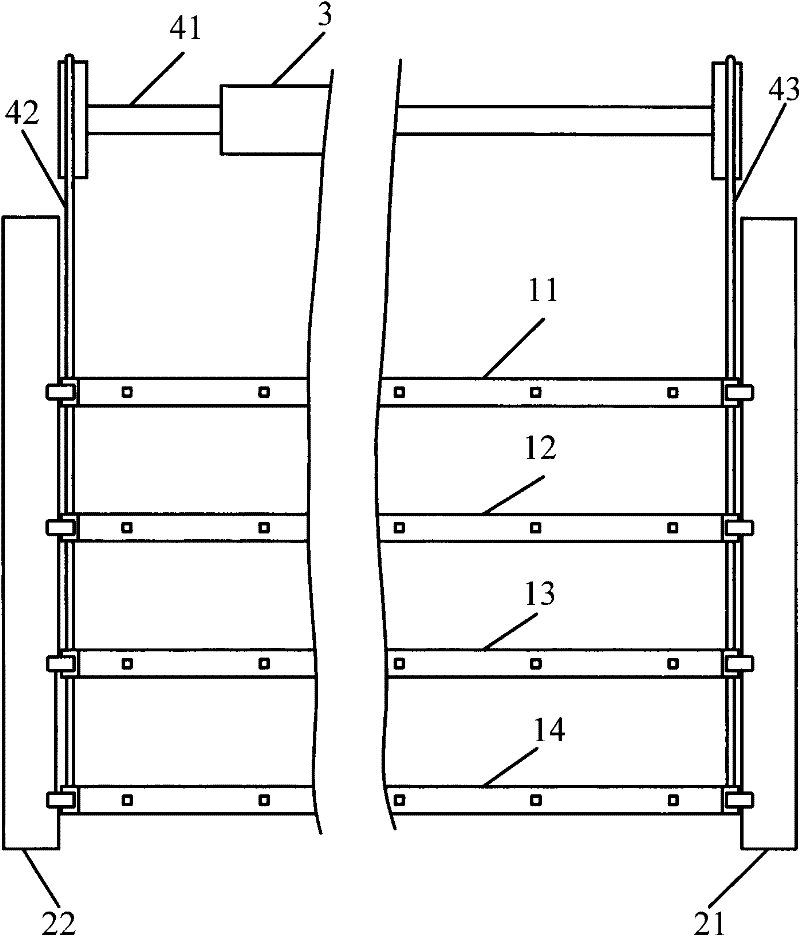
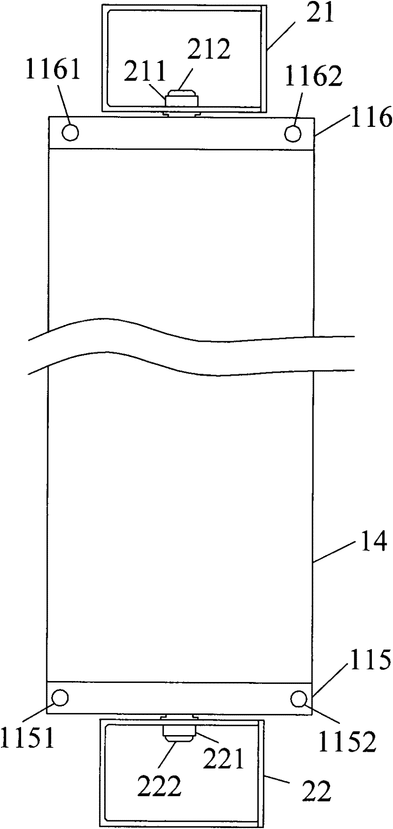
[0036] figure 1 This is a front view of the louvered display screen in this embodiment, where the louvered display screen in this embodiment includes 4 blades 11, 12, 13, and 14, 2 support frames 21 and 22, a motor 3, and a drive shaft 41 and ladder ropes 42 and 43.
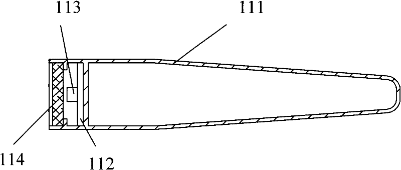
[0037] The motor 3 is fixedly connected to the transmission shaft 41, the ladder ropes 42 and 43 are fixedly connected to the transmission shaft 41, and each blade is provided with 10 LED display elements ( figure 1 Not all shown in), the motor 3 serves as a rotating unit, so the rotation of the motor 3 drives the transmission shaft 41 to drive the rotation of the blades. In addition, other forms of rotating components can also be used to form the rotating unit. For example, hydraulic motors.
[0038] In this embodiment, the length of the blades 11, 12, 13, and 14 is 2 meters, the LED display elements are arranged on the blades at a distance of 200 mm, and the length of the support frames 21 and 22 is 1 meter, so The...
no. 2 example
[0047] Figure 5 Shown here is a front view of the louvered display screen of this embodiment. The difference between the louvered display screen in this embodiment and the first embodiment is that the support frames 21 and 22 are eliminated, and a lifting blade is added. The lifting units of 11, 12, 13, and 14, the lifting unit is a motor 5, and a transmission unit for lifting the blade, the transmission unit includes a transmission shaft 61 and a traction component, the transmission unit here can also Other methods are used to drive the rotation of the blades 11, 12, 13, and 14, such as transmission shafts and connecting rods. In addition, a suspension rope 72 at the right end of the blade and a suspension rope at the left end of the blade ( Figure 5 (Not shown in), one end of the suspension rope is fixed to the blade, and the other end is fixed on the top plane. In this embodiment, the traction member is the guide rope 62 ( Figure 5 (Not shown in) and the guide rope 63 on t...
PUM
| Property | Measurement | Unit |
|---|---|---|
| Length | aaaaa | aaaaa |
| Length | aaaaa | aaaaa |
| Length | aaaaa | aaaaa |
Abstract
Description
Claims
Application Information
 - R&D Engineer
- R&D Manager
- IP Professional
- Industry Leading Data Capabilities
- Powerful AI technology
- Patent DNA Extraction
Browse by: Latest US Patents, China's latest patents, Technical Efficacy Thesaurus, Application Domain, Technology Topic, Popular Technical Reports.
© 2024 PatSnap. All rights reserved.Legal|Privacy policy|Modern Slavery Act Transparency Statement|Sitemap|About US| Contact US: help@patsnap.com


