
Elastic coupling for motor

A technology for elastic couplings and motor shafts, which is applied in the direction of elastic couplings, couplings, electrical components, etc., to achieve the effects of simple structure, increased ability to transmit torque, and convenient wearing parts

Inactive Publication Date: 2014-04-09
NIDEC BEIJING DRIVE TECH CO LTD +2
View PDF7 Cites 0 Cited by
  • Summary
  • Abstract
  • Description
  • Claims
  • Application Information

AI Technical Summary

Problems solved by technology

[0005] The main purpose of the present invention is to overcome the defects of the existing elastic couplings for motors, and provide a new type of elastic couplings for motors. The technical problem to be solved is to make the elastic couplings Compact structure, more reliable transmission performance, can effectively isolate the vibration generated by the motor and reduce noise, and facilitate the replacement of vulnerable parts

Method used


Image

  • Elastic coupling for motor
  • Elastic coupling for motor
  • Elastic coupling for motor

Examples


Embodiment 1

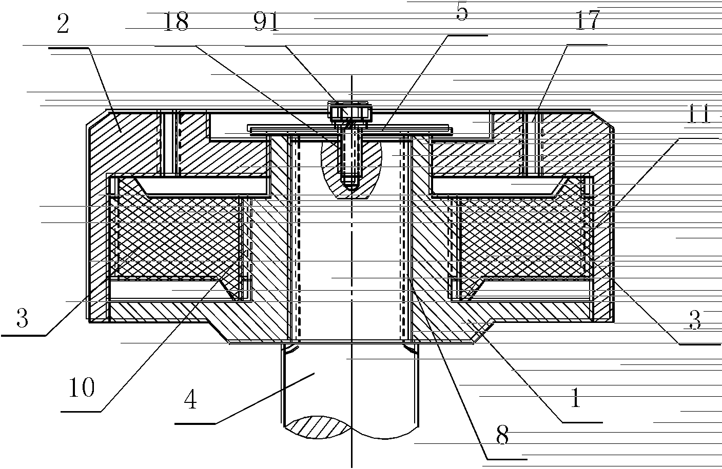
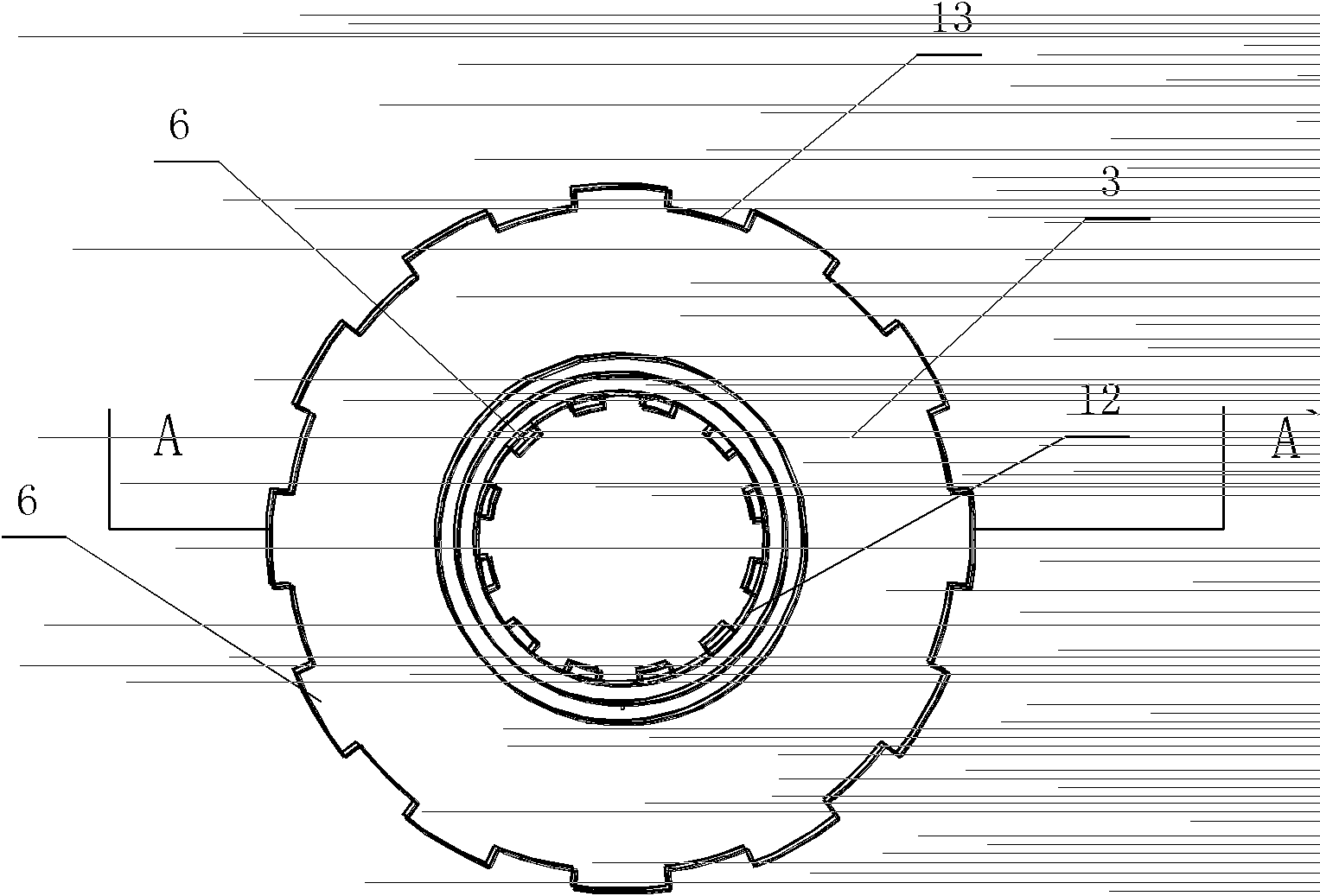
[0034] Such as figure 1 , image 3 with Figure 4 As shown, the elastic coupling for the motor includes a ring shape and coaxial shells 1 , 2 and elastic gears 3 , and a spline inner hole 8 is provided at the center of the shell 1 . The carapace shell 1 is sleeved on the motor shaft 4 through the spline inner hole 8 , and is fixed on the motor shaft 4 through the baffle plate 5 arranged at the end of the motor shaft 4 . A fixing hole 18 is provided at the center of the end of the motor shaft 4 , and the baffle plate 5 is fixed on the shaft end of the motor shaft 4 by fixing bolts 91 . The B housing 2 is arranged between the A housing 1 and the baffle plate 5, and the A housing 1 and the B housing 2 are connected in transmission through the elastic gear 3 arranged therebetween. Specifically, on the inner cylindrical surface 12 of the elastic gear 3 and the radial direction of the outer cylindrical surface 13 are provided with elastic gear radial power transmission teeth 6, a...

Embodiment 2

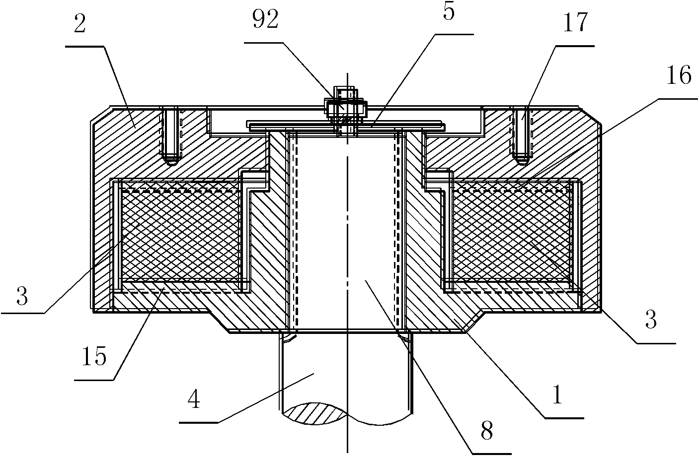
[0041] Such as figure 2 , Figure 5 , Image 6 As shown, the difference between this embodiment and Embodiment 1 is that the transmission between the elastic gear 3 and the shells of A and B in this embodiment is through being arranged on the end face of the elastic gear 3, and with the elastic gear 3 It is realized by the power transmission teeth on the contact surface of the A and B housings whose end faces are in contact. Concretely, the upper cylindrical end surface 19 and the lower cylindrical end surface 20 of the elastic gear 3 are equipped with elastic gear axial force transmission teeth 14 in the axial direction; The contact surfaces of the first case 1 and the second case 2 contacted by 20 are respectively provided with the axial force transmission teeth 15 of the case A and the axial force transmission teeth 16 of the second case, and the upper cylindrical end surface 19 and the lower cylindrical end surface 20 of the elastic gear 3 The axial force transmission ...


PUM


Abstract

The invention belongs to the field of mechanical transmission device, and particularly relates to an elastic coupling for a motor, which comprises a first casing, a second casing and an elastic gear, wherein the first casing and the second casing are annular and coaxial. The first casing is connected onto a motor shaft in a sleeved mode and fixed on the motor shaft through a blocking plate arranged at the end of the motor shaft. The second casing is arranged between the first casing and the blocking plate, the first casing is in transmission connection with the second casing through the elastic gear arranged between the first casing and the second casing, gaps are reserved between the second casing and the first casing and the blocking plate in the axial direction, and a screw hole for fixing a load shaft flange plate is arranged on the second casing. Compared with the prior art, the elastic coupling for the motor is compact in structure, reliable in transmission performance and capable of effectively isolating vibration produced by the motor and reducing noise simultaneously, and easily-damaged parts are convenient to replace.

Description

technical field [0001] The invention belongs to the field of mechanical transmission devices, and in particular relates to an elastic coupling for a motor. Background technique [0002] In some technical fields, the speed range of the motor is very wide, and the output torque ripple of the motor is relatively large at low speed, and the vibration and noise generated are quite large. For example, when the vibration and noise of the motor on an electric vehicle are too large, not only will the driver and passengers feel very uncomfortable, but also the impact on the rotating shaft is relatively large, and in severe cases, it will cause permanent damage to the rotating shaft. [0003] In order to reduce the vibration and noise caused by the motor, a simple and effective solution is to change the rigid coupling used between the motor load shaft and the motor load shaft into an elastic coupling, and rely on the elastic body to absorb or release potential energy. Torque ripple on...

Claims


Application Information

Patent Timeline
Patent Type & Authority Patents(China)
IPC IPC(8): F16D3/64F16D3/66F16D3/68H02K7/10
Inventor 张华平李永辉高超裘锦灼
Owner NIDEC BEIJING DRIVE TECH CO LTD
Learn More