Eureka AIR delivers breakthrough ideas for toughest innovation challenges, trusted by R&D personnel around the world.

Cooling fan for traction converter of high-speed electric locomotive

A technology for traction converters and electric locomotives, which is applied to machines/engines, components of pumping devices for elastic fluids, mechanical equipment, etc., can solve the problems of low temperature shock resistance and high-speed vibration and avoid losses , The effect of reducing separation loss and leakage loss

Inactive Publication Date: 2012-07-04
洛阳北玻三元流风机技术有限公司 +1
View PDF5 Cites 5 Cited by
  • Summary
  • Abstract
  • Description
  • Claims
  • Application Information

AI Technical Summary

Problems solved by technology

At present, domestic fans cannot meet the needs of low-temperature shock resistance and high-speed vibration

Method used


Image

  • Cooling fan for traction converter of high-speed electric locomotive
  • Cooling fan for traction converter of high-speed electric locomotive
  • Cooling fan for traction converter of high-speed electric locomotive

Examples


Embodiment Construction

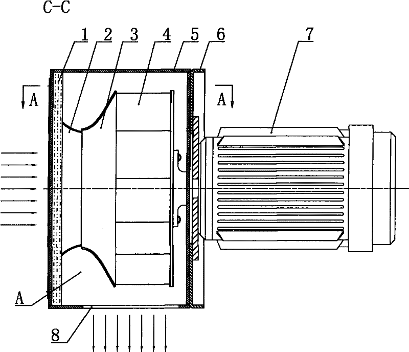
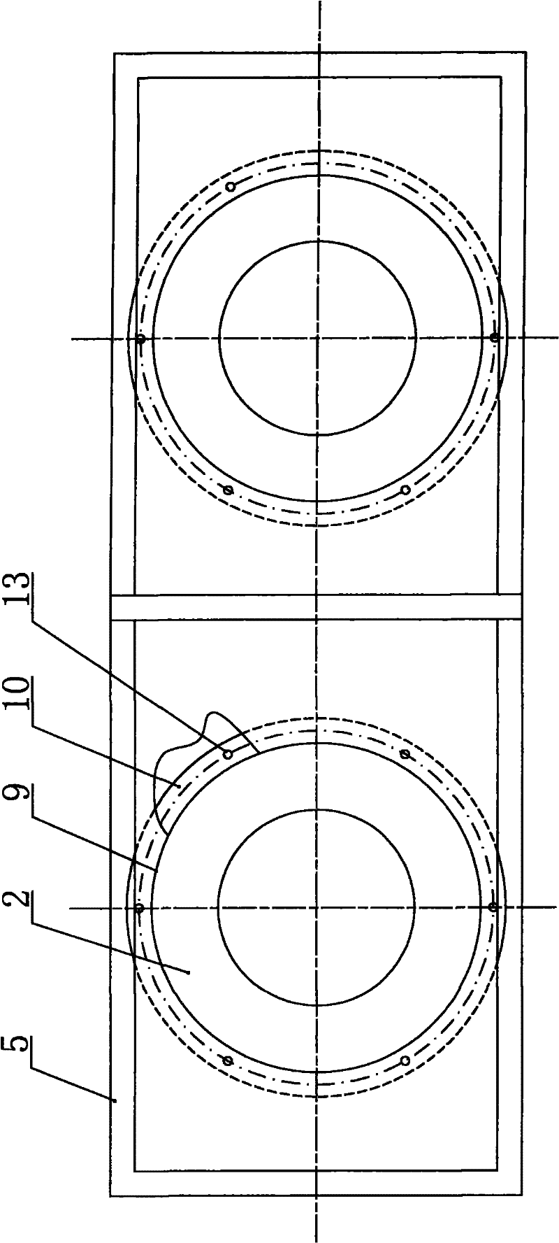
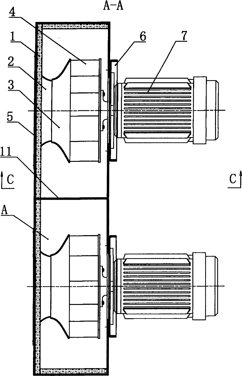
[0030] see Figure 1 to Figure 6 , a cooling fan for a high-speed electric locomotive traction converter of the present invention is combined with an impeller 4, a motor 7, and a motor mounting plate 6 on a rectangular box body 5 of an existing cooling system,

[0031] In the middle of this casing 5, divide into two independent cavities A with dividing plate 11, respectively house a motor 7 at the rear side of each this cavities A, at the front side and the lower side of each these cavities A The sides are respectively provided with an air inlet 9 and an air outlet 8. The rear side of each cavity A is respectively connected to the front end of a motor 7, and an impeller 4 is respectively arranged in each cavity A and is coaxially installed on the output shaft of the motor 7. When working, they all rotate counterclockwise (matched with the entire cooling system) without interfering with each other.

[0032] The impeller 4 is composed of a front disc 3, a rear disc 41 and a pl...


PUM


Abstract

The invention relates to a cooling fan for a traction converter of a high-speed electric locomotive. The cooling fan comprises a rectangular box body (5), wherein a clapboard (11) is arranged at the middle of the box body (5) to divide the box body (5) into two independent cavities, a motor (7) is installed at rear side of each cavity, and an air inlet (9) and an air outlet (8) are respectively arranged at the front side and the lower side of each cavity. The cooling fan is characterized in that the rear side of each cavity is connected with the front end of the motor (7), an impeller (4) is arranged in each cavity and is coaxially installed on the output shaft of the motor (7), and two impellers (4) rotate counterclockwise during working so as not to mutually intervene. The cooling fan provided by the invention is mainly used for cooling the traction converters of motor trains with speed per hour of more than 380 km / h, and can satisfy the requirements of resisting low-temperature impact and high-speed vibration.

Description

technical field [0001] The invention relates to a fan for cooling the traction converter system of a CRH-380B high-speed electric locomotive. Specifically, the air volume generated by the fan overcomes the pressure of the pipe network resistance of the entire system, and passes through the radiator in the traction converter system. Take away the heat generated when the locomotive traction converter is working, so as to ensure the stable operation of the entire high-speed electric locomotive traction converter system. It is mainly used for cooling the traction converter of the EMU train with a speed of 380km / h or more. Background technique [0002] In October 2004, China signed a contract with Siemens for a batch of extended version ICE3 trains as the operating models of China High Speed ​​Railway (CRH). According to the contract, a few trains were directly exported from Germany to China, and most of the trains were assembled in China by Tangshan Railway Vehicle Co., Ltd. of...

Claims


Application Information

Patent Timeline
Patent Type & Authority Applications(China)
IPC IPC(8): F04D25/08F04D29/28F04D29/44
Inventor 李建森郭双任文道王磊
Owner 洛阳北玻三元流风机技术有限公司
Why Eureka
Eureka Blog
Learn More