
Battery electricity-taking device for mobile phone extension device

A technology for expanding devices and taking electrical appliances, which is applied to battery pack components, circuits, electrical components, etc., and can solve the problem that the radio frequency module cannot be identified to provide power, the expansion module cannot provide power, and there is no space reserved for identifying the radio frequency module to supply power, etc. problem, to achieve the effect of meeting the demand for power supply

Active Publication Date: 2015-04-29
EASTCOMPEACE TECH
View PDF8 Cites 0 Cited by
  • Summary
  • Abstract
  • Description
  • Claims
  • Application Information

AI Technical Summary

Problems solved by technology

For example, if you want to realize smart payment, you need the support of RF-SIM card, and you need a module that can identify the radio frequency tag to support it. Since the identification radio frequency module itself needs power supply, however, there is no reserved space in the mobile phone for the identification of the radio frequency module. There is no space for power supply, so it is unable to provide corresponding power for the identification radio frequency module
There are also corresponding problems in the expansion of other smart phone functions, that is, the corresponding power cannot be provided for the expansion module, so that the user's demand for smart phone expansion cannot be met.

Method used


Image

  • Battery electricity-taking device for mobile phone extension device
  • Battery electricity-taking device for mobile phone extension device

Examples


Embodiment Construction

[0019] The following will clearly and completely describe the technical solutions in the embodiments of the present invention with reference to the accompanying drawings in the embodiments of the present invention. Obviously, the described embodiments are only some, not all, embodiments of the present invention. Based on the embodiments of the present invention, all other embodiments obtained by persons of ordinary skill in the art without making creative efforts belong to the protection scope of the present invention.

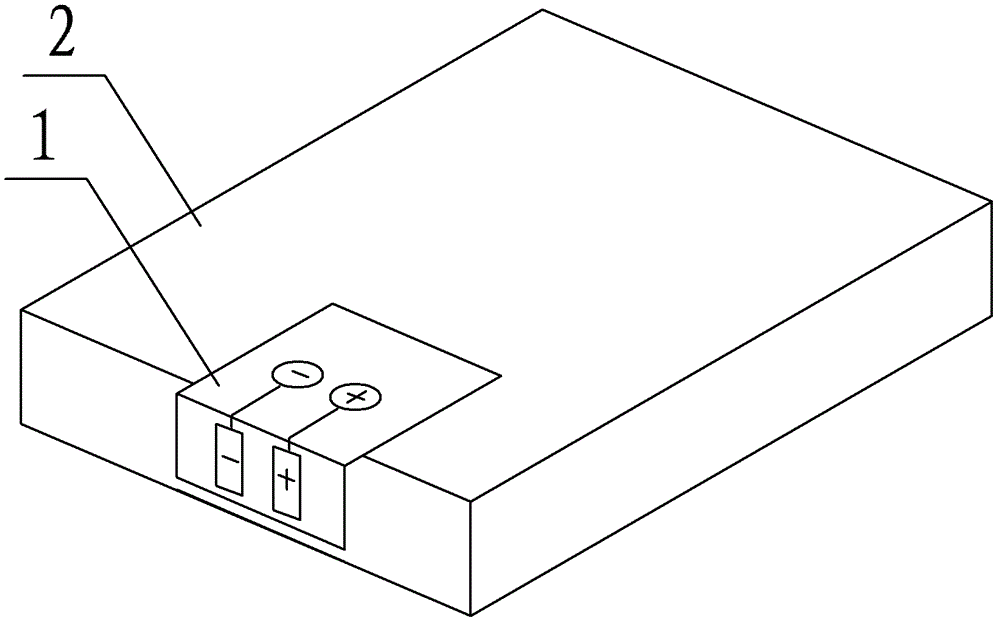
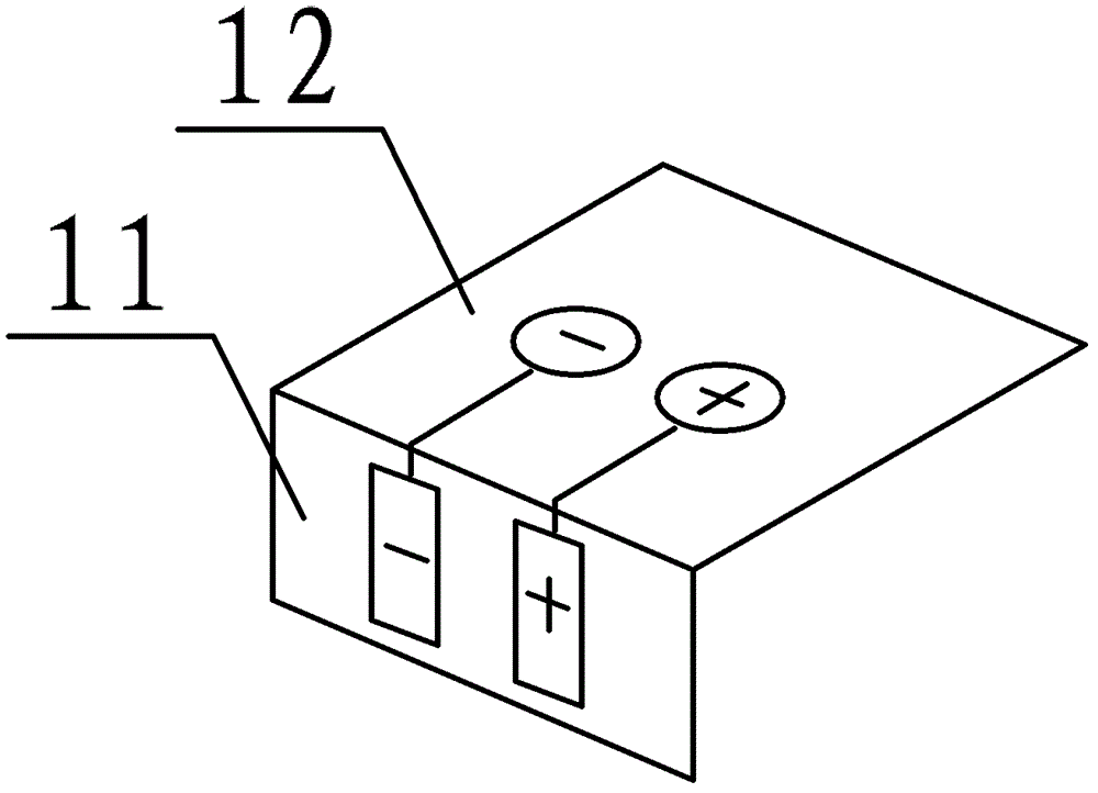
[0020] An embodiment of the present invention provides a battery pick-up device for a mobile phone extension device, including a power pick-up piece and a power transmission piece connected to each other; The extreme end is connected to the positive end of the power transmission sheet, and the negative end of the power-taking sheet is connected to the negative end of the power transmission sheet; the positive end of the power-taking sheet can be connected to th...


PUM


Abstract

The invention discloses a battery electricity-taking device for a mobile phone extension device. The battery electricity-taking device comprises an electricity-taking piece and an electricity transmission piece which are mutually connected and respectively provided with anode terminals and cathode terminals, wherein, the anode terminal and cathode terminal of the electricity-taking piece are respectively connected with the anode terminal and cathode terminal of the electricity-transmission piece; the anode terminal of the electricity-taking piece is respectively connected with the electricity-taking anode terminal of the mobile phone and the anode terminal of the battery; the cathode terminal of the electricity-taking piece is respectively connected with the electricity-taking cathode terminal of the mobile phone and the cathode terminal of the battery; the anode terminal and cathode terminal of the electricity-transmission piece are connected with the anode terminal and cathode terminal of the mobile phone extension device; the positive-negative poles of the electricity-taking piece are arranged at the connection parts of the electricity-taking positive-negative poles of the mobile phone and the positive-negative poles of the battery, so that the mobile phone can be powered normally by the battery under the condition that the electrical quantity of the battery can be obtained; and besides, the positive-negative poles of the mobile phone extension device and the positive-negative poles of the electricity-transmission piece are connected so as to meet the power supply requirement of the mobile phone extension device.

Description

technical field [0001] The invention relates to the field of smart phones, and more specifically, relates to a battery extractor of a mobile phone extension device. Background technique [0002] With the popularization and enhancement of functions of modern smart phones, people have a strong demand for applications such as electronic payment, product authenticity identification and real-time positioning. [0003] For the expansion of additional functions of smart phones, the current mobile phone suppliers do not give timely updates on the hardware. For example, if you want to realize smart payment, you need the support of RF-SIM card, and you need a module that can identify the radio frequency tag to support it. Since the identification radio frequency module itself needs power supply, however, there is no reserved space in the mobile phone for the identification of the radio frequency module. There is no space for power supply, so the corresponding power cannot be provided...

Claims


Application Information

Patent Timeline
Patent Type & Authority Patents(China)
IPC IPC(8): H01M2/20
CPCY02E60/10
Inventor 党飞
Owner EASTCOMPEACE TECH
Learn More