
Automatic leakproof pressure gauge seat

A pressure gauge, automatic technology, applied in the direction of measuring fluid pressure, measuring devices, instruments, etc., can solve the problems of secondary injury accidents, waste of resources, pollution of the environment, etc., to prevent combustion or explosion accidents, avoid environmental pollution, convenient Remove the effect of replacement

Inactive Publication Date: 2012-06-20
鞍山市特种设备监督检验所
View PDF7 Cites 2 Cited by
  • Summary
  • Abstract
  • Description
  • Claims
  • Application Information

AI Technical Summary

Problems solved by technology

The pressure gauge seats currently used are generally straight-through. Once the pressure gauge is damaged and falls off, the operator must rush to the scene in time and manually close the valve on the pressure gauge connection. However, in some places, the operator cannot quickly approach the accident point, resulting in special equipment. The medium inside is sprayed out from the pressure gauge seat under the action of internal pressure, causing secondary injury accidents
Among them, a considerable part of the pressure vessels contain toxic, flammable, explosive, highly corrosive gases or liquefied gases. (It does happen in actual operation), which will cause a large amount of harmful media to overflow, and even cannot carry out emergency repair work at all, which not only causes waste of resources, but also seriously pollutes the environment

Method used


Image

  • Automatic leakproof pressure gauge seat
  • Automatic leakproof pressure gauge seat

Examples


Embodiment Construction

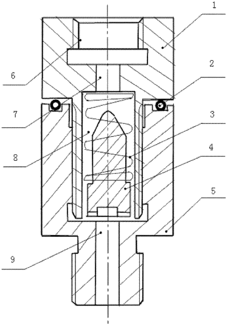
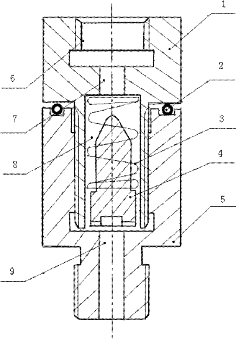
[0013] Automatic bleed-off pressure gauge seats, such as figure 1 As shown, it includes a seat body composed of an upper shell 1 and a lower shell 5, a pressure spring 3, and a sealing float 4. The seat body is transparent up and down, and a central chamber 8 is provided in the middle of the seat body, and a sealing float is arranged in the central chamber 8. 4. The sealing float 4 adopts a solid structure; the top of the central chamber 8 is provided with an outlet channel 7, the bottom end is provided with an inlet channel 9, and the top of the outlet channel 7 is provided with a seat groove 6 for installing a pressure gauge; the sealing float 4 has three sections Type structure, the top of which is conical, and the bottom of the conical structure is a stepped columnar structure; the inner diameter of the outlet channel 7 is smaller than the outer diameter of the widest part of the sealing float 4 cone; the outer side of the sealing float 4 is covered with a pressure spring 3...


PUM


Abstract

The invention relates to an automatic leakproof pressure gauge seat. The automatic leakproof pressure gauge seat comprises a seat body, a sealing floater and a pressure spring; the seat body is vertically thorough; a center chamber is arranged at the middle part of the seat body; the sealing floater is arranged in the center chamber; a flow outlet passage is arranged at the top end of the center chamber; a flow inlet passage is arranged at the bottom end of the center chamber; a seat groove for mounting a pressure gauge is arranged at the top end of the flow outlet passage; the sealing floater is of a three-section structure, the top of the three-section structure is of a cone-shaped structure, and the part of the three-section structure, which is below the cone-shaped structure, is of a stepped cylindrical structure; the inside diameter of the flow outlet passage is less than the outside diameter of the widest part of a cone of the sealing floater; the pressure spring is sleeved on the outer side of the sealing floater; and the bottom end of the pressure spring supports against the stepped position of a stepped cylinder of the sealing floater, and the top end of the pressure spring is fixedly arranged at the top face of the center chamber. The automatic leakproof pressure gauge seat has the advantages of reasonable structure and design, safe and reliable performance, avoidance of the leakage of a media pipeline when the pressure gauge is damaged, and capability of being widely applied to various pressure gauges for pressure vessels and pressure piping.

Description

technical field [0001] The invention relates to a protection device, in particular to an automatic leak-resistance pressure gauge seat. Background technique [0002] Pressure gauges are one of the commonly used safety accessories for special equipment such as boilers and pressure vessels. As pressure-bearing special equipment, pressure vessels are widely used in petrochemical, pharmaceutical, refrigeration and other production fields. The pressure gauge seat is an important connection between the pressure gauge and the body of the special equipment. Generally, it is connected vertically to the pressure gauge seat at an appropriate position on the pressure vessel body, and the pressure gauge is installed on the top of the pressure gauge seat. The pressure gauge seats currently used are generally straight-through. Once the pressure gauge is damaged and falls off, the operator must rush to the scene in time and manually close the valve on the pressure gauge connection. However,...

Claims


Application Information

Patent Timeline
Patent Type & Authority Applications(China)
IPC IPC(8): G01L19/00
Inventor 魏振江侯学军付建国张辉杨中建李博才振宇
Owner 鞍山市特种设备监督检验所
Learn More