Bike saddle fixture
A technology for bicycles and fixtures, applied in bicycle saddles, bicycle accessories, transportation and packaging, etc., can solve the problems of large force structure, inconvenient and complicated installation, and achieve improved assembly efficiency, convenient loading and unloading, and simple structure Effect
- Summary
- Abstract
- Description
- Claims
- Application Information
AI Technical Summary
Problems solved by technology
Method used
Image
Examples
Embodiment 1
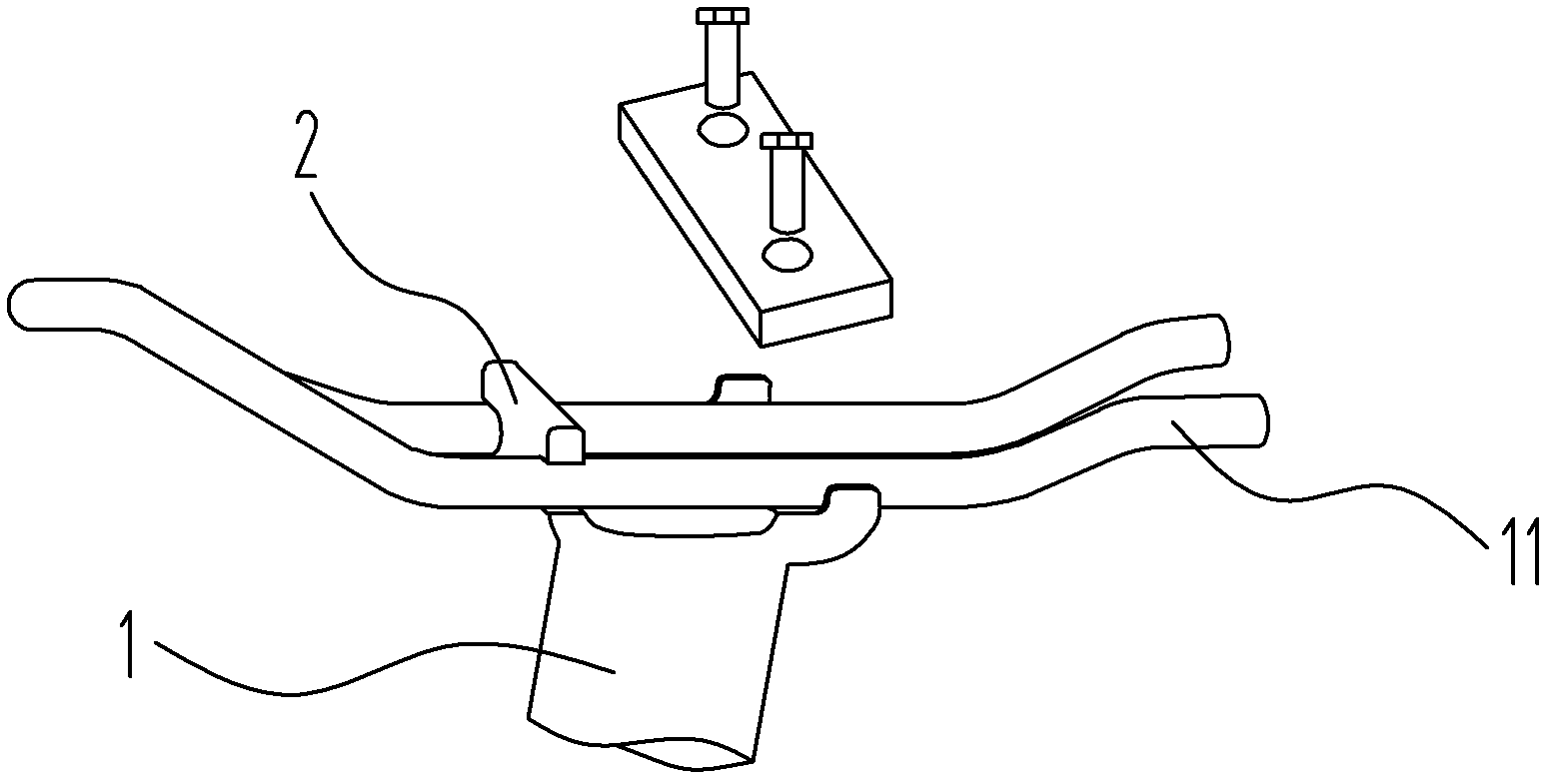
[0029] Embodiment one: see figure 1 As shown, a bicycle seat fixture, the front side of the upper end of the seat tube 1 is provided with two transverse grooves 210 with a distance equal to the width of the seat cushion bow, and the rear side of the upper end of the seat tube 1 is provided with two longitudinal grooves 220. A locking device is pressed above the longitudinal groove 220. Preferably, the locking device is a pressing plate mounted on the upper end of the seat tube 1. The upper end of the seat tube 1 is provided with a threaded hole, and the pressing plate is connected with two bolts. The seat tube forms a fixed connection.
[0030] The bicycle seat clamp is composed of a transverse groove 210, a longitudinal groove 220 and a locking device.
Embodiment 2
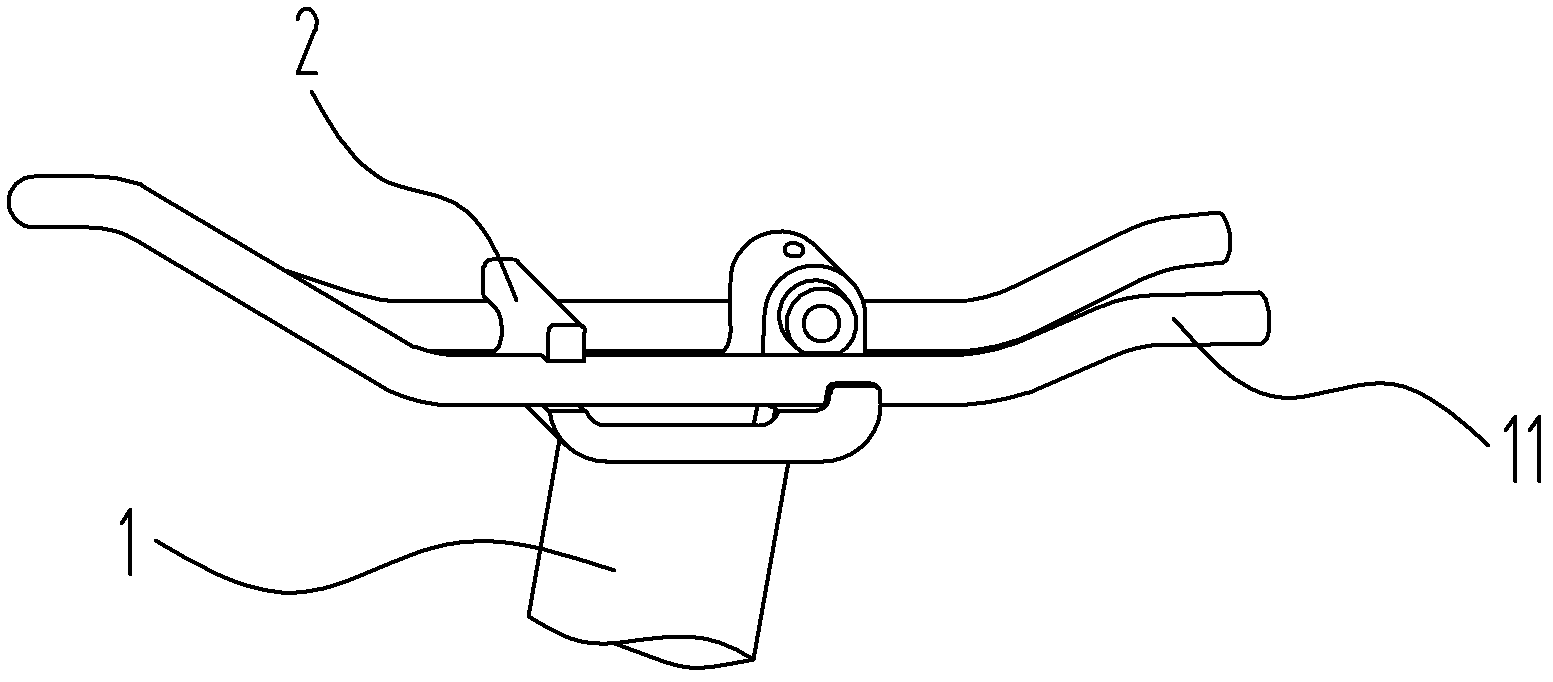
[0031] Embodiment two: see figure 2 ~ Figure 7 As shown, a bicycle seat fixture, the upper end of the seat tube 1 is fixed with a base plate 20 and two flanges located on the front and rear sides of the base plate. Side 21 and rear flange 22, wherein the two ends of the front flange 21 are respectively provided with a transverse groove 210 on the side end surface of the flange, which is used to clamp the front end of the seat cushion bow 11; the rear flange 22 Both ends respectively define a longitudinal groove 220 on the upper end surface of the flange, which is used to clamp the rear end of the seat cushion bow 11 .
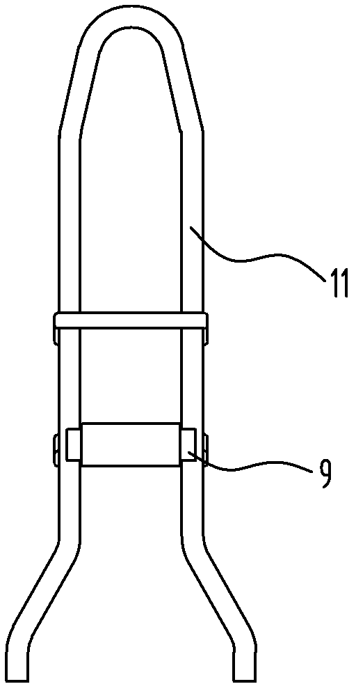
[0032] A locking device is fixedly connected to the rear flange 22, and the locking device consists of a pin hole arranged between the two longitudinal grooves 220, and two locking pins 9 inserted from both ends of the pin hole respectively. The inner walls of the two locking pins 9 are provided with internal threads that rotate in opposite directions, and...
Embodiment 3
[0042] Embodiment three: as Figure 8 and Figure 9 As shown, a bicycle saddle fixture, the upper end of the saddle tube 1 is fixed with a base plate 20 and two flanges located on the front and rear sides of the base plate 20. According to the usage of the saddle clamp 2, the two flanges are respectively the front Flange 21 and rear flange 22, wherein the two ends of the front flange 21 are respectively provided with a transverse groove 210 on the side end surface of the front flange, which is used to clamp the front end of the seat cushion bow 11; Both ends of 22 are respectively provided with a longitudinal groove 220 whose mouth is located on the upper end surface of the rear flange, for clamping the rear end of the cushion bow 11 .
[0043] The said rear flange 22 is fixedly connected with a locking device, and said locking device is arranged on the pin hole between the two longitudinal grooves 220, the elastic body 8 is inserted from the two ends of the rear flange 22 re...
PUM
 Abstract
Description
Claims
Application Information
 - R&D
- Intellectual Property
- Life Sciences
- Materials
- Tech Scout
- Unparalleled Data Quality
- Higher Quality Content
- 60% Fewer Hallucinations
Browse by: Latest US Patents, China's latest patents, Technical Efficacy Thesaurus, Application Domain, Technology Topic, Popular Technical Reports.
© 2025 PatSnap. All rights reserved.Legal|Privacy policy|Modern Slavery Act Transparency Statement|Sitemap|About US| Contact US: help@patsnap.com


