
Crawler shelf for vending machine

A vending machine and shelf technology, applied in the field of vending machines, can solve the problems affecting the shipment of goods, accidental shipment of goods, complicated operations, etc., and achieve the effect of improving the success rate of shipments, avoiding accidental shipments, and ensuring normal operation.

Active Publication Date: 2012-06-13
TIANJIN LEIYUNFENG TECH
View PDF4 Cites 16 Cited by
  • Summary
  • Abstract
  • Description
  • Claims
  • Application Information

AI Technical Summary

Problems solved by technology

The existing problems are: 1. Since the crawler adopts a closed standard part, the crawler is transmitted by friction between the driving shaft and the driven shaft, but the length of the rack crawler cannot be adjusted, resulting in inconsistent travel speeds of the goods placed on the crawler due to different weights. Affect product shipment; 2. After the shelf is shipped, the motor is usually reversed to push the shipping push plate into the inner end, and then new products are placed on the shelf
Because the circuit using the motor inversion method is very complicated, it not only increases the cost of the vending machine, but also the operation is more complicated, and it is inconvenient to use; Therefore, it is necessary to manually check the sales of goods frequently to facilitate replenishment
In addition, external shocks and tilts often cause unexpected shipments of goods, and also cause economic losses to operators
For this reason, this type of vending machine is not suitable for the fast-paced modern life of today's society, and also affects the normal function of the vending machine.

Method used


Image

  • Crawler shelf for vending machine
  • Crawler shelf for vending machine
  • Crawler shelf for vending machine

Examples


Embodiment Construction

[0028] The present invention will be further described in detail below in conjunction with the accompanying drawings and through specific embodiments. The following embodiments are only descriptive, not restrictive, and cannot limit the protection scope of the present invention.

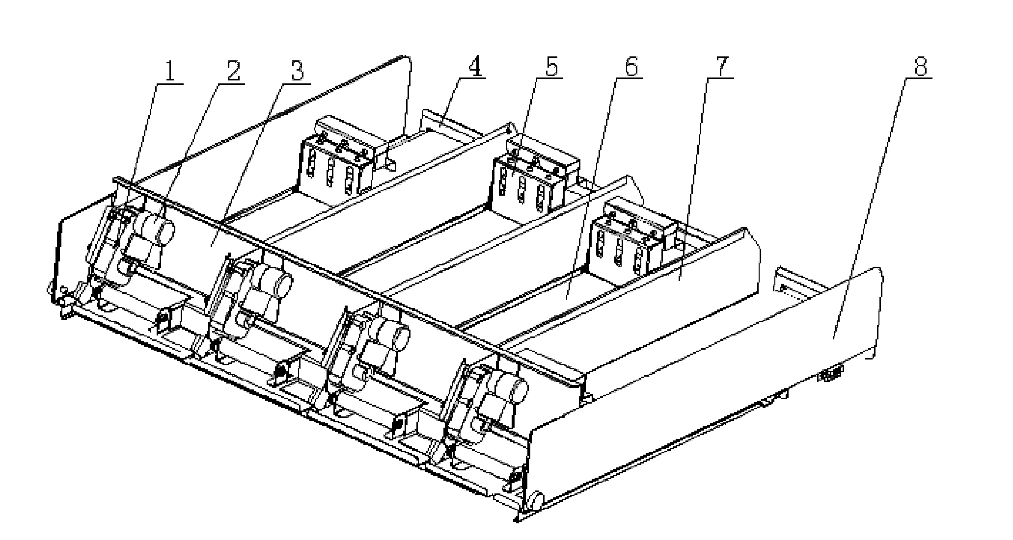
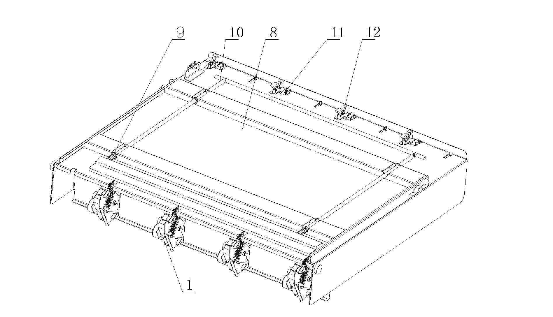
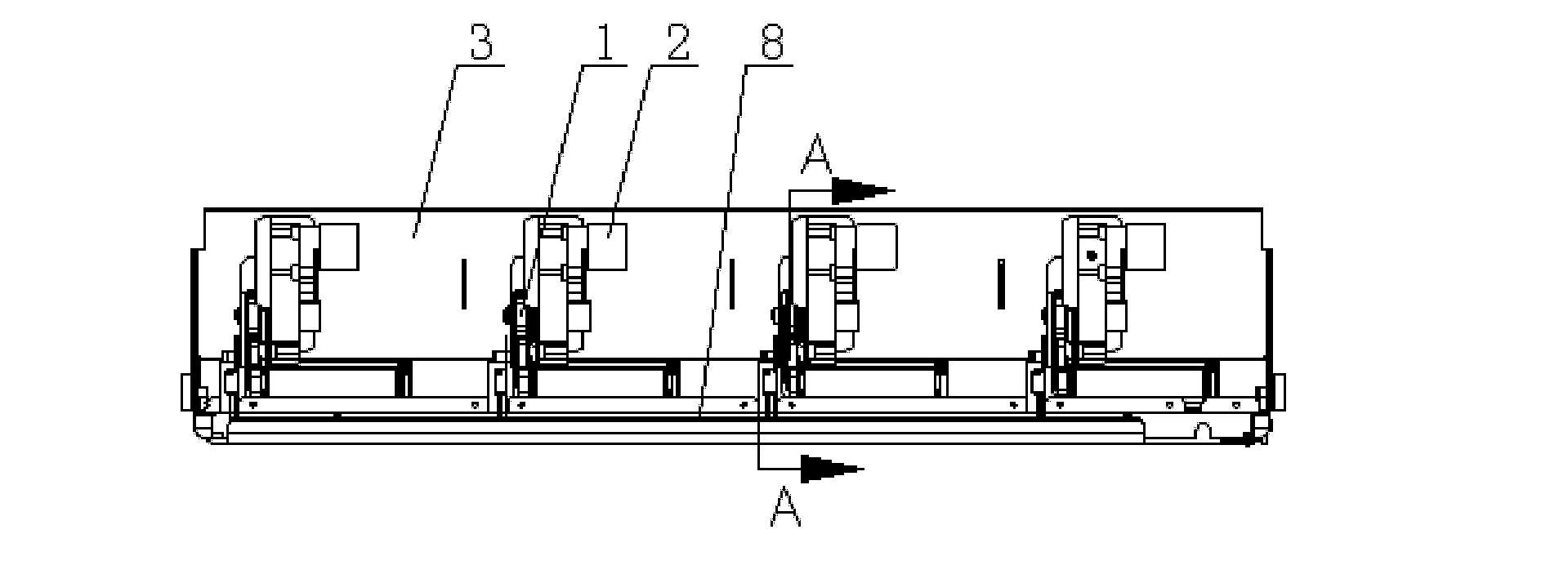
[0029] A crawler shelf for a vending machine, comprising a shelf main body 8, a single shelf unit and a drive unit, the driving units are installed evenly at intervals through fixed transmission protective plates 3 at the rear of the shelf main body, and on the shelf main body at the front end of the transmission protective plate A single shelf unit is installed corresponding to the drive unit, and the drive unit provides transmission power for the single shelf unit.

[0030] In this embodiment, four single shelf units are installed on the main body of the shelf, and partitions 7 are installed between adjacent single shelf units. The number and length of the single shelf units are set according to act...


PUM


Abstract

The invention relates to a crawler shelf for a vending machine, which comprises a shelf main body, a single shelf unit and a driving unit and is characterized in that (1) a lower bottom plate of the shelf main body is provided with a U-shaped clutch rod; (2) an installation plate is fixedly arranged on the rear portion of a goods output push plate, a clamp plate is arranged in a space formed between the installation plate and the goods output push plate, and two ends of a crawler are positioned on the clamp plate; (3) a goods output press plate is hinged on a driven shaft at the front end of the crawler, a goods output detection travel switch is arranged at the lower bottom of the self corresponding to the turning position of the goods output press plate, and a non-goods detection travel switch is arranged at the lower bottom of the self corresponding to the moving position of the goods output push plate. The crawler shelf for the vending machine is simple in structure, scientific in design, novel and wide in application prospects.

Description

technical field [0001] The invention belongs to the field of vending machines, and relates to shelves installed at intervals in the vending machine, in particular to a crawler shelf of the vending machine. Background technique [0002] At present, automatic vending machines have been popularized in various places, which are convenient for people to buy goods by themselves. The vending machine usually consists of a vending box, a shelf, a coin slot and an outlet. The goods are placed on the slides of the shelves in the vending box, and the goods are pushed out and dropped to the outlet through the propulsion device installed on the inside of the shelf. Take it out from the cargo port. The existing problems are: 1. Since the crawler adopts a closed standard part, the crawler is transmitted by friction between the driving shaft and the driven shaft, but the length of the rack crawler cannot be adjusted, resulting in inconsistent travel speeds of the goods placed on the crawler...

Claims


Application Information

Patent Timeline
Patent Type & Authority Applications(China)
IPC IPC(8): A47F1/00G07F11/00
Inventor 李德政魏韧张宝强
Owner TIANJIN LEIYUNFENG TECH
Learn More