Light-emitting diode (LED) control circuit

A technology of light-emitting diodes and control circuits, which is applied in the arrangement of electric lamp circuits, light sources, electric light sources, etc., and can solve problems such as single brightness and brightness adjustment.

Active Publication Date: 2015-03-25
STATE GRID CORP OF CHINA
View PDF3 Cites 0 Cited by
  • Summary
  • Abstract
  • Description
  • Claims
  • Application Information

AI Technical Summary

Problems solved by technology

However, most of the products of general LED lamps are designed with a single brightness, and there is no way to adjust different brightness according to the needs of users.

Method used


Image

  • Light-emitting diode (LED) control circuit
  • Light-emitting diode (LED) control circuit
  • Light-emitting diode (LED) control circuit

Examples


Embodiment Construction

[0028] Below in conjunction with accompanying drawing and preferred embodiment the present invention is described in further detail:

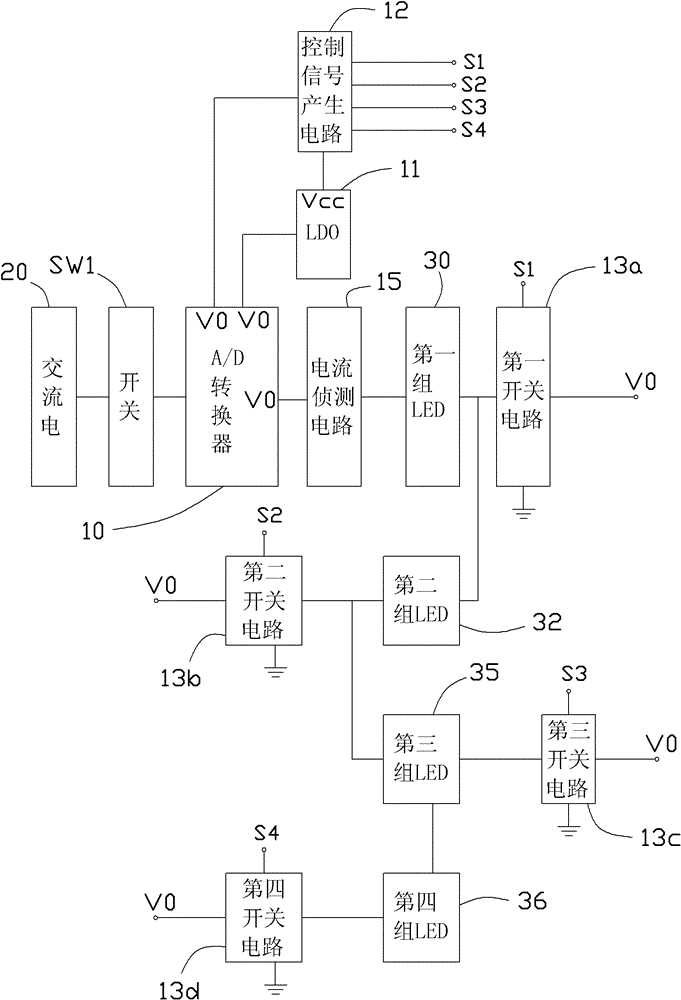
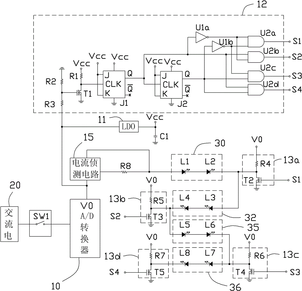
[0029] Please refer to figure 1 and figure 2 , the light-emitting diode control circuit of the present invention can be used to adjust the brightness of a light-emitting diode lamp, and its preferred embodiment includes a switch SW1, an alternating current (Alternating Current, AC)-direct current (Direct current, DC) converter (A / D Converter) 10 , a low dropout regulator (LDO) 11 , a control signal generating circuit 12 , first to fourth switch circuits 13 a - 13 d and a current detection circuit 15 . In this embodiment, the LED lamp tube includes eight light-emitting diodes L1-L8 connected in series, wherein the light-emitting diodes L1 and L2 are the first group of light-emitting diodes 30, the light-emitting diodes L3 and L4 are the second group of light-emitting diodes 32, and the light-emitting diodes L5 and L6 are the third group of li...


PUM


Abstract

A light-emitting diode (LED) control circuit comprises: a switch, a control signal generation circuit, a voltage conversion unit and N switch circuits. The voltage conversion unit is used to convert a voltage of a direct-current power supply into another direct-current voltage so as to provide a working voltage for the control signal generation circuit. The control signal generation circuit outputs different control signals from an output terminal according to a switch action so as to correspondingly control conduction or disconnection of the N switch circuits. Therefore, the direct current power supply can provide power for the corresponding LED so as to adjust brightness of the tube of the LED. By using the LED control circuit, the brightness of the tube of the LED can be adjusted.

Description

technical field [0001] The invention relates to a light emitting diode control circuit. Background technique [0002] At present, more and more light-emitting diodes are used in lighting equipment. However, most of the products of general LED lamps are designed with a single brightness, and there is no way to adjust different brightness according to the needs of users. Contents of the invention [0003] In view of the above, it is necessary to provide a light emitting diode control circuit with adjustable brightness. [0004] A light-emitting diode control circuit, used to adjust the brightness of a light-emitting diode tube, the light-emitting diode tube includes N groups of light-emitting diodes sequentially connected in series, the light-emitting diode control circuit includes a switch, a control signal generation circuit, a voltage A conversion unit and N switch circuits, the first end of the switch is connected to a DC power supply, the second end is connected to th...

Claims


Application Information

Patent Timeline
Patent Type & Authority Patents(China)
IPC IPC(8): H05B37/02
Inventor 谢明志
Owner STATE GRID CORP OF CHINA
Why Eureka
Try Eureka